

Downhole deburring tool
- Summary
- Abstract
- Description
- Claims
- Application Information
AI Technical Summary
Benefits of technology
Problems solved by technology
Method used
Image

Examples
Embodiment Construction
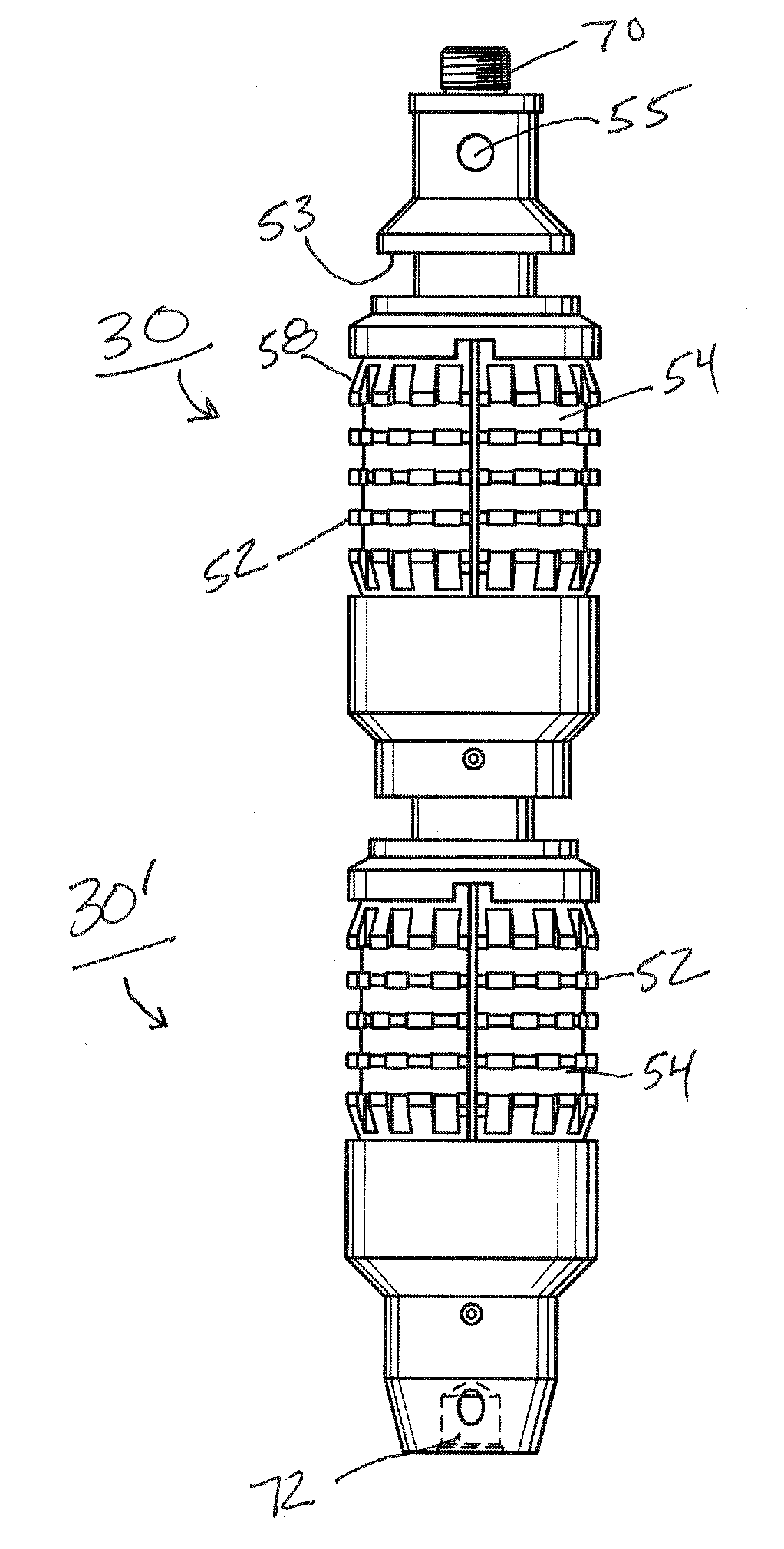
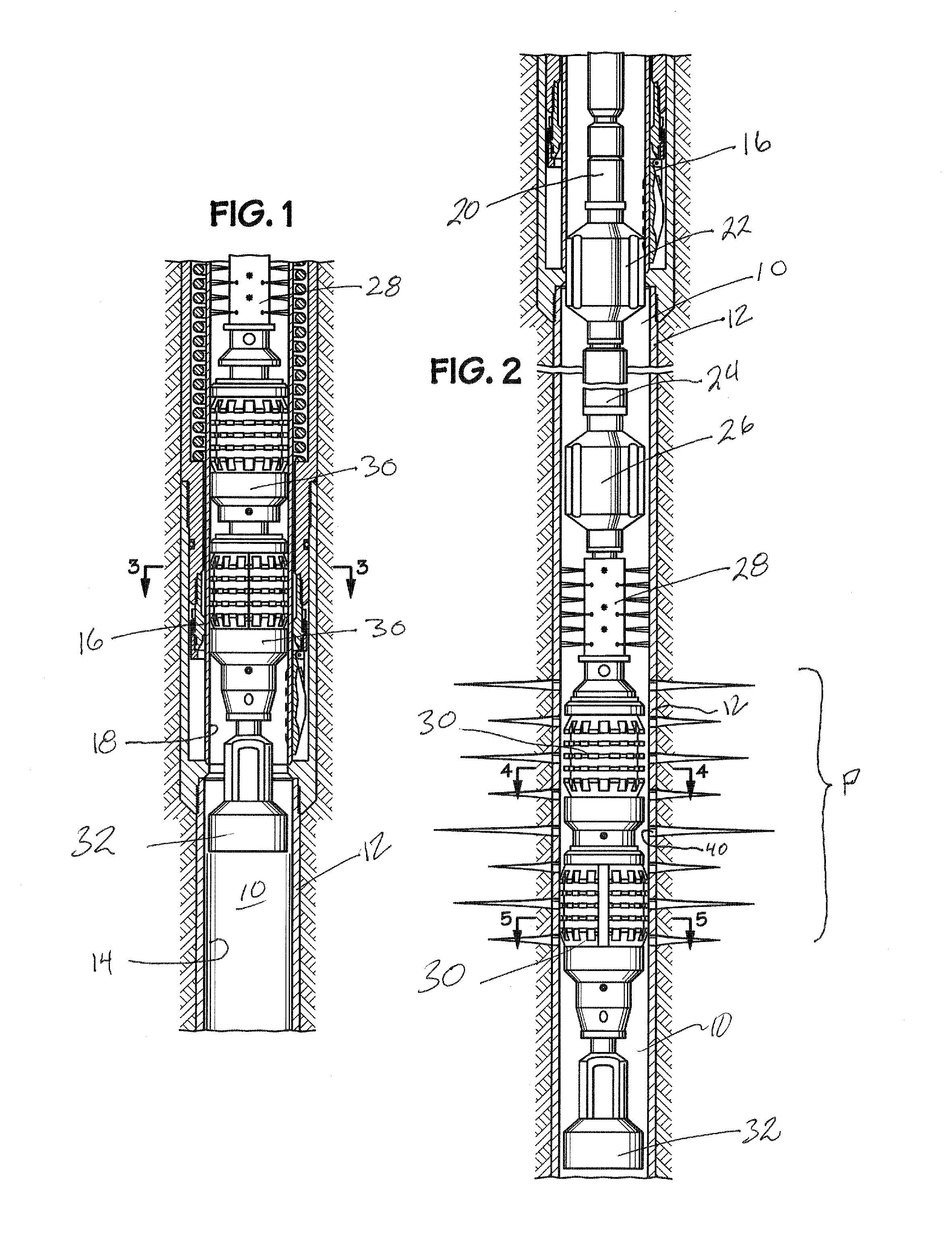
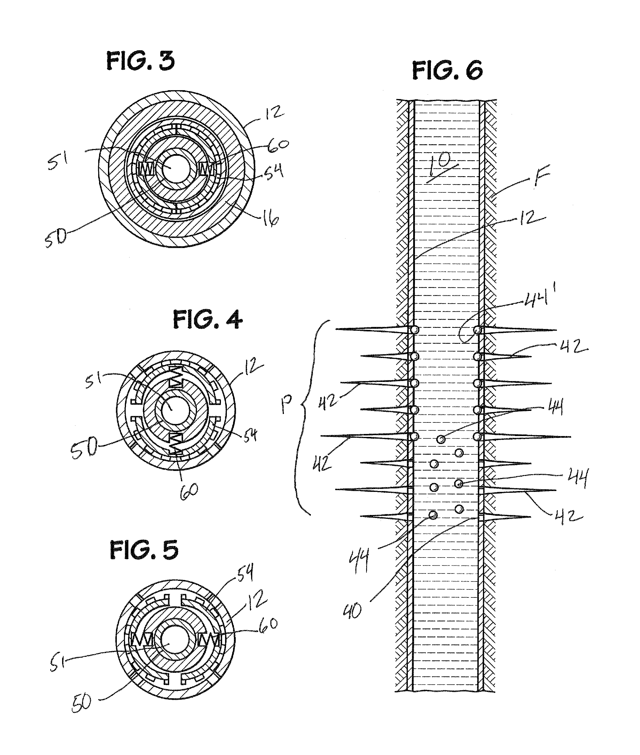
[0026]In order to allow hydrocarbons to flow from a formation into a cased wellbore, the casing may be perforated to create holes in the casing or liner to achieve efficient communication between the reservoir and the wellbore. The characteristics and placement of the communication paths (perforations) can have significant influence on the productivity of the well. A perforating gun assembly with the appropriate configuration of shaped explosive charges and the means to verify or correlate the correct perforating depth can be deployed on wireline, tubing or coiled tubing.
[0027]Hydraulic fracturing is a stimulation treatment routinely performed on oil and gas wells in low-permeability reservoirs. Specially engineered fluids are pumped at high pressure and rate into the reservoir interval to be treated, causing a vertical fracture to open. The wings of the fracture extend away from the wellbore in opposing directions according to the natural stresses within the formation. Proppant, su...
PUM
| Property | Measurement | Unit |
|---|---|---|
| Diameter | aaaaa | aaaaa |
| Resilience | aaaaa | aaaaa |
Abstract
Description
Claims
Application Information