Probe-connection-type pogo pin and manufacturing method thereof
Active Publication Date: 2014-12-11
IWIN
View PDF3 Cites 18 Cited by
Summary
Abstract
Description
Claims
Application Information
AI Technical Summary
This helps you quickly interpret patents by identifying the three key elements:
Problems solved by technology
Method used
Benefits of technology
[0024]According to embodiments of the present invention, it is possible to apply the pogo pin to highly integrated electronic parts and test equipment by eliminating an external body, which is used to surround a spring in a conventional pogo pin, to reduce the outside diameter of the pogo pin and thus reduce the interval between pogo pins.
Problems solved by technology
However, the conventional pogo pin is disadvantageous in that the conventional pogo pin is formed in such a manner that the cylindrical body is provided on the outside of the spring.
In other words, the conventional pogo pin needs to have an outside diameter as large as both the outside diameter of the spring and the thickness of the cylindrical body containing the spring, which makes it difficult to reduce the outside diameter of the pogo pin to below a predetermined size.
Accordingly, the conventional pogo pin is disadvantageous in that since the conventional pogo pin has an electrical path through the uppe
Method used
Image
Click on the blue label to locate the original text in one second.
Reading with bidirectional positioning of images and text.
Examples
Example
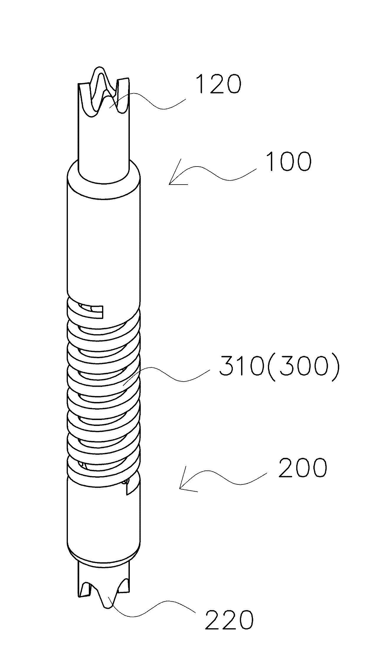
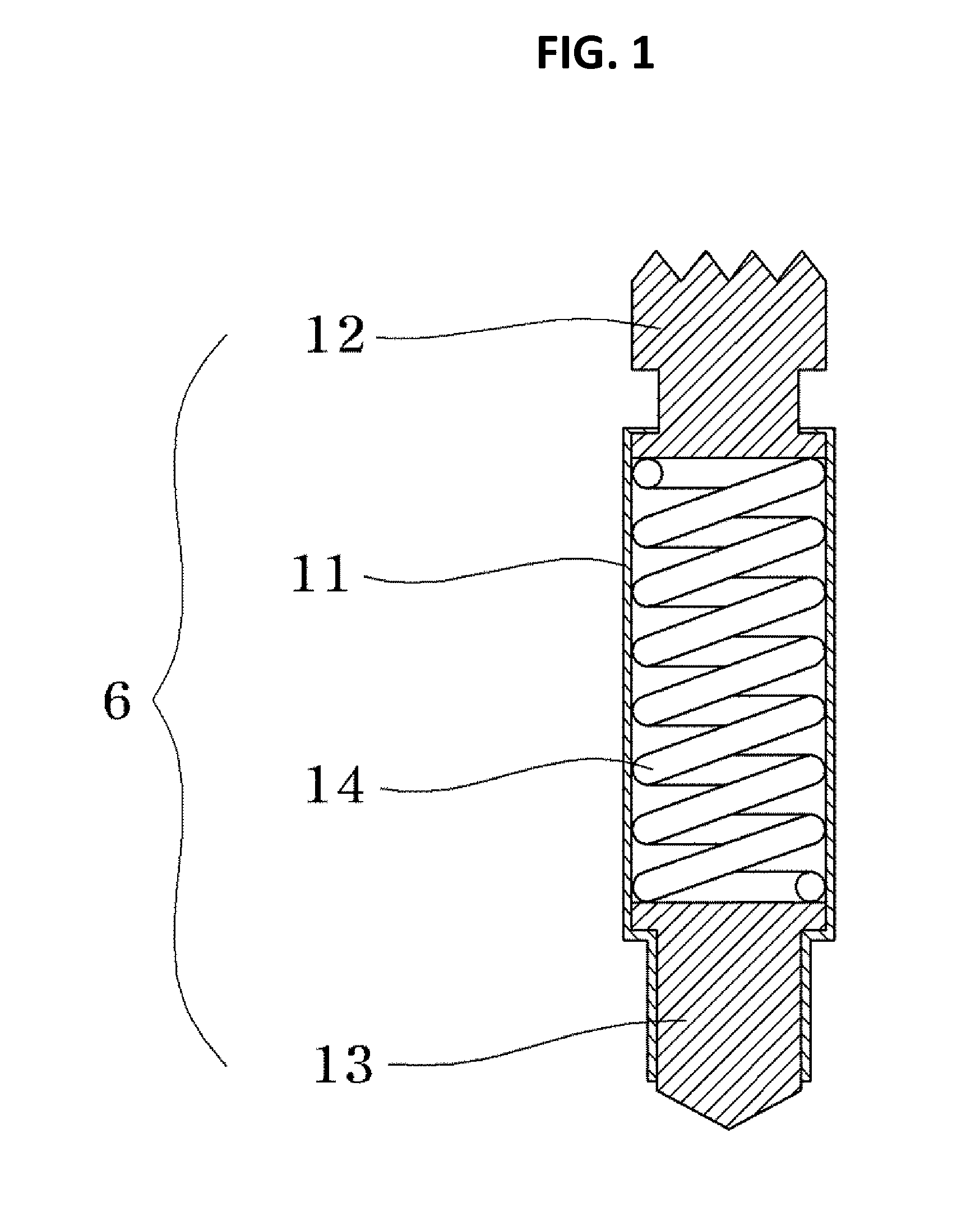
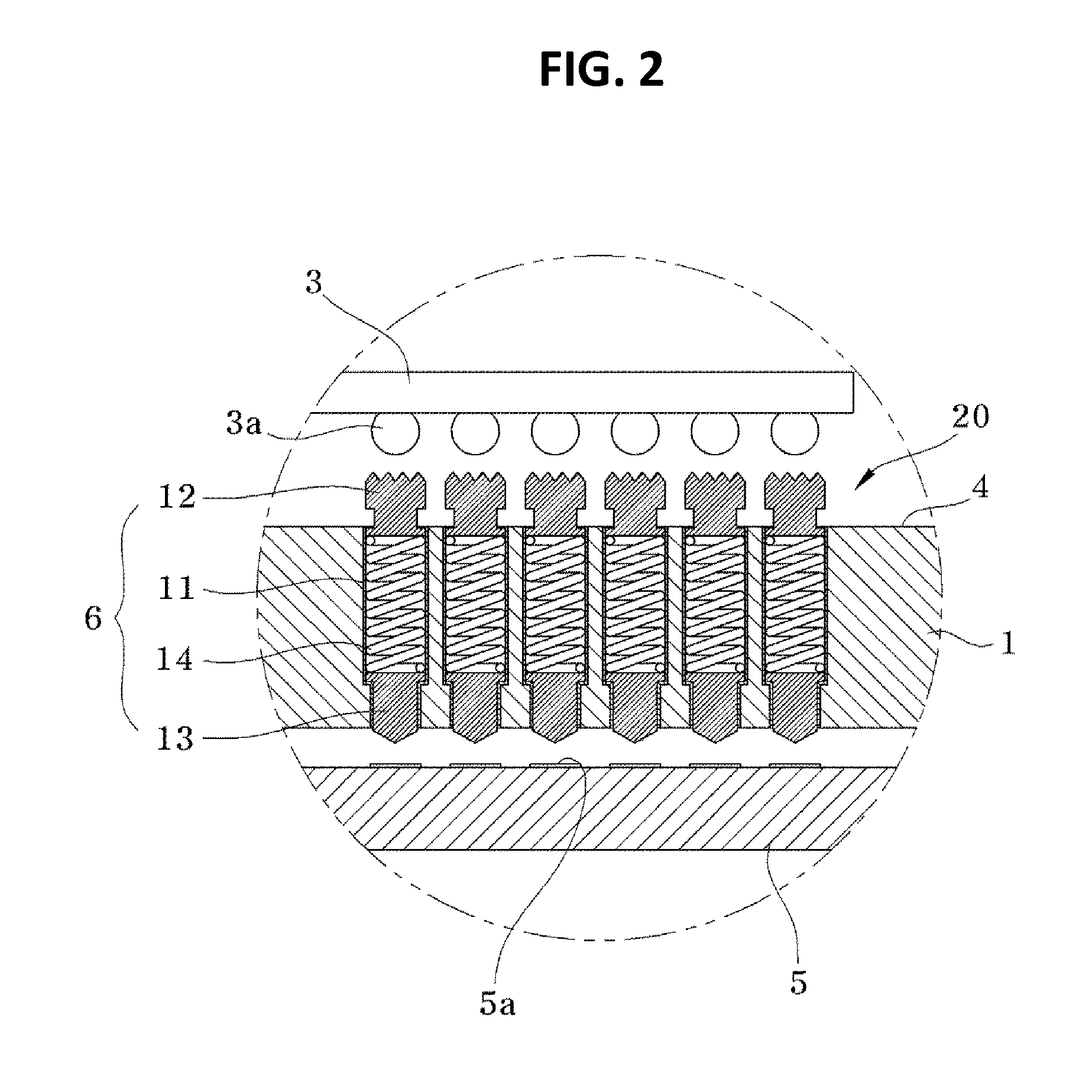
[0034]The present invention provides a pogo pin including an upper probe part, a lower probe part, and an elastic part made of a spring, which is characterized in that a part of or a whole of each of the upper and lower probe parts is shaped in cylindrical shape and there is no additional body surrounding the elastic part.
[0035]Exemplary embodiments of the present invention will now be described in detail with reference to the accompanying drawings. Description of well-known structures may be omitted to enhance clarity and conciseness in the event that the description of well-known structures makes the technical idea of the present invention unclear or indefinite.
[0036]As shown in FIGS. 3A and 4A, a pogo pin includes an upper probe part 100, a lower probe part 200, and an elastic part 300 which is positioned between the upper probe part and the lower probe part. The pogo pin may be formed by separately making the upper probe part 100, the lower probe part 200, and the elastic part 3...
PUM
Property
Measurement
Unit
Force
aaaaa
aaaaa
Elasticity
aaaaa
aaaaa
Abstract
The present invention relates to a pogo pin including a probe part and an elastic part, and more particularly, to a probe-connection-type pogo pin including a cylindrical upper probe part, an elastic part, and a cylindrical lower probe part, which are made in one body, to transmit electrical signals between semiconductor wafers, LCD modules, semiconductor packages, electronic parts such as a variety of sockets, etc. Accordingly, it is possible to reduce the manufacturing process and the manufacturing cost, reduce the outside diameter of the pogo pin by making the elastic part formed to surround the cylindrical lower probe part, and reduce the loss and distortion of electrical signal by allowing the upper probe part and the lower probe part to come in surface contact with each other.
Description
TECHNICAL FIELD[0001]The following description relates to a pogo pin including a probe part and an elastic part, and more particularly, to a probe-connection-type pogo pin including cylindrical upper and lower probe parts and an elastic part, which are made in one body, to transmit electrical signals between semiconductor wafers, LCD modules, semiconductor packages, electronic parts, such as a variety of sockets, etc.BACKGROUND ART[0002]Spring probe pins, also known as pogo pins, have been widely used in inspection equipment for semiconductor wafers, LCD modules, camera modules, image sensors, and semiconductor packages, a variety of sockets, battery connectors of mobile phones, etc.[0003]As shown in FIG. 1, a conventional pogo pin includes an upper probe 12, a lower probe 13, a spring 14, which is formed to apply elastic force on the upper probe 12 and the lower probe 13, and a cylindrical body 11, which contains a lower portion of the upper probe 12, an upper portion of the lower ...
Claims
Application Information
Patent Timeline
Application Date:The date an application was filed.
Publication Date:The date a patent or application was officially published.
First Publication Date:The earliest publication date of a patent with the same application number.
Issue Date:Publication date of the patent grant document.
PCT Entry Date:The Entry date of PCT National Phase.
Estimated Expiry Date:The statutory expiry date of a patent right according to the Patent Law, and it is the longest term of protection that the patent right can achieve without the termination of the patent right due to other reasons(Term extension factor has been taken into account ).
Invalid Date:Actual expiry date is based on effective date or publication date of legal transaction data of invalid patent.