Vibration damping device for elevator
a technology of vibration damping device and elevator, which is applied in the direction of electric devices, coils, elevators, etc., can solve the problems of hindrance to car comfort and transverse vibration in the car, and achieve the effect of preventing minute slippage in the coil
- Summary
- Abstract
- Description
- Claims
- Application Information
AI Technical Summary
Benefits of technology
Problems solved by technology
Method used
Image

Examples
first embodiment
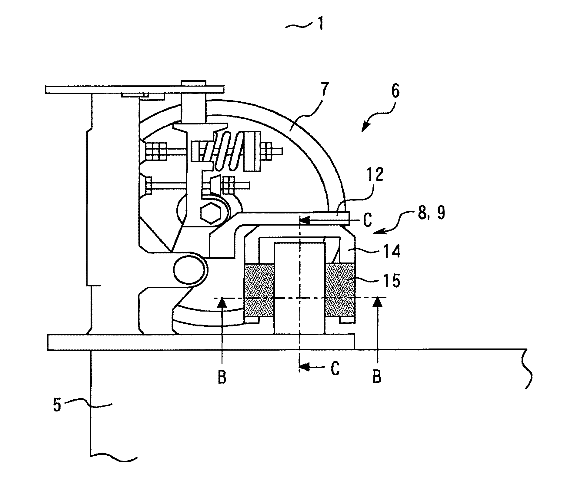
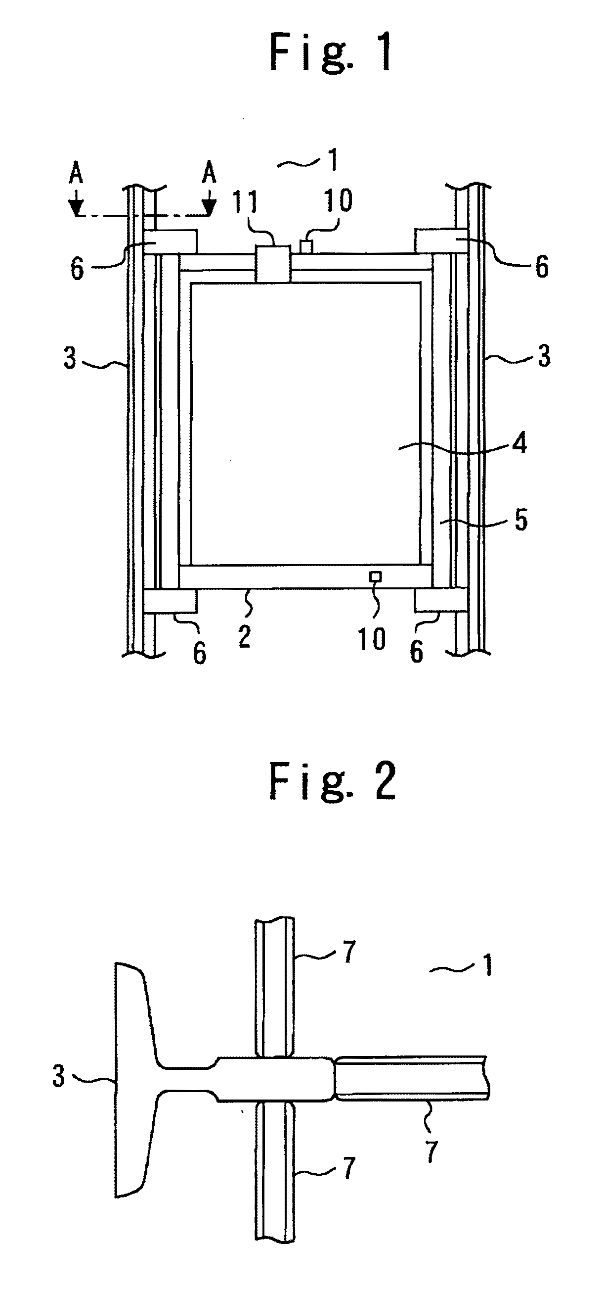
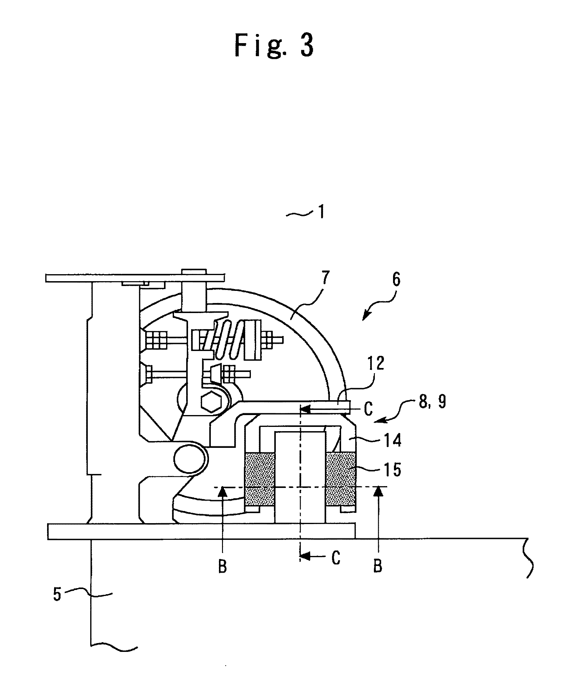
[0036]FIG. 1 is a front view of an elevator car provided with a vibration damping device in a first embodiment according to the present invention, FIG. 2 is a view taken along the line A-A of FIG. 1, FIG. 3 is a view showing the details of a guiding device shown in FIG. 1, FIG. 4 is a view taken along the line B-B of FIG. 3, and FIG. 5 is a view taken along the line C-C of FIG. 3.
[0037]In FIGS. 1 to 5, reference numeral 1 denotes an elevator shaft, 2 denotes an elevator car moving up and down in the shaft 1, 3 denotes a pair of guide rails erected in the shaft 1.
[0038]The car 2 constitutes an elevating body of the elevator, and includes, for example, a car room 4, a car frame 5 for supporting the car room 4 and the like, and guiding devices 6 provided on both sides of the top portion and bottom portion of the car frame 5. The guiding device 6 is used for guiding the up and down movement of the car 2 by engaging with the guide rail 3. This guiding device 6 is provided with rollers 7 ...
second embodiment
[0057]FIG. 12 is a detail view of portion D in a second embodiment according to the present invention, and FIG. 13 is a view for explaining the details of the bobbin in the second embodiment according to the present invention.
[0058]In FIGS. 12 and 13, in the winding surface 16 of the bobbin 14, a groove 21 corresponding to the wire diameter of the wire 18 is formed so as to be equally spaced in the direction in which the wire 18 is wound. The groove 21, like the groove 19, has a curved shape forming a part of a circle in the transverse cross section. Also, the groove 21 has an opening width (W2 in FIG. 13) narrower than the wire diameter of the wire 18, and has a curve greater than that of the wire 18 in the transverse cross section.
[0059]In the first embodiment, the space between the grooves 19 is equal to the opening width W1. On the other hand, in the second embodiment, the space between the grooves 21 is set so as to be larger than the opening width W2. Therefore, between the ad...
third embodiment
[0062]FIG. 14 is a detail view of portion D in a third embodiment according to the present invention, and FIG. 15 is a view for explaining the details of the bobbin in the third embodiment according to the present invention.
[0063]In FIGS. 14 and 15, in the winding surface 16 of the bobbin 14, a groove 23 corresponding to the wire diameter of the wire 18 is formed so as to be equally spaced in the direction in which the wire 18 is wound. The groove 23 has a rectangular shape having a width (W3 in FIG. 15) narrower than the wire diameter of the wire 18 in the transverse cross section. Since the groove 23 has the rectangular shape, between the adjacent grooves 23, a flat part 24 is naturally formed along the lengthwise direction of the groove 23.
[0064]Since the groove 23 has the above-described shape, the wire 18a forming the innermost layer of the coil 15 is fixed to the bobbin 14 in the state of being in contact with both edge portions (boundary portions between the groove 23 and the...
PUM
 Abstract
Description
Claims
Application Information
 - R&D
- Intellectual Property
- Life Sciences
- Materials
- Tech Scout
- Unparalleled Data Quality
- Higher Quality Content
- 60% Fewer Hallucinations
Browse by: Latest US Patents, China's latest patents, Technical Efficacy Thesaurus, Application Domain, Technology Topic, Popular Technical Reports.
© 2025 PatSnap. All rights reserved.Legal|Privacy policy|Modern Slavery Act Transparency Statement|Sitemap|About US| Contact US: help@patsnap.com