Sheet discharging tray device and image forming system provided therewith

a technology of image forming system and discharging tray, which is applied in the directions of transportation and packaging, thin material processing, and article delivery, etc., can solve the problems of reducing productivity and likely deviation of sheet alignment, and achieve the effect of reducing the distance between adjoining sheets and the linear speed of sheets

Active Publication Date: 2012-05-03
KONICA MINOLTA BUSINESS TECH INC
View PDF10 Cites 8 Cited by
  • Summary
  • Abstract
  • Description
  • Claims
  • Application Information

AI Technical Summary

Benefits of technology

[0013]6. In the sheet discharging tray device of any one of the aforementioned Items 2 through 5, the controller preferably changes the operation status of the sheet discharging tray by reducing either the moving amount of the sheet discharging tray or the moving speed of the sheet discharging tray.
[0014]7. In the sheet discharging tray device of any one of the aforementioned Items 2 through 6, a further conveyance path for conveying sheets is provided to convey sheets to this sheet discharging section including the sheet discharging section. In this case, the controller preferably changes the discharge status of the aforementioned sheets by using at least one of the following methods: a method of reducing the linear speed of the sheets along the conveyance path; a method of reducing the distance between adjoining sheets, with the sheet linear speed along the conveyance path being kept unchanged; and a method wherein a preceding sheet is temporarily retained in the sheet conveyance path leading to the sheet discharging section, and a succeeding sheet is then placed on top of the preceding sheet, this step being followed by a step of conveying the sheet again.

Problems solved by technology

The sheet discharging tray device of this type has a problem in that a sheet alignment deviation is likely to occur due to the tray shift operation.
However, this may result in reduced productivity.

Method used


Image

  • Sheet discharging tray device and image forming system provided therewith
  • Sheet discharging tray device and image forming system provided therewith
  • Sheet discharging tray device and image forming system provided therewith

Examples


embodiment 1

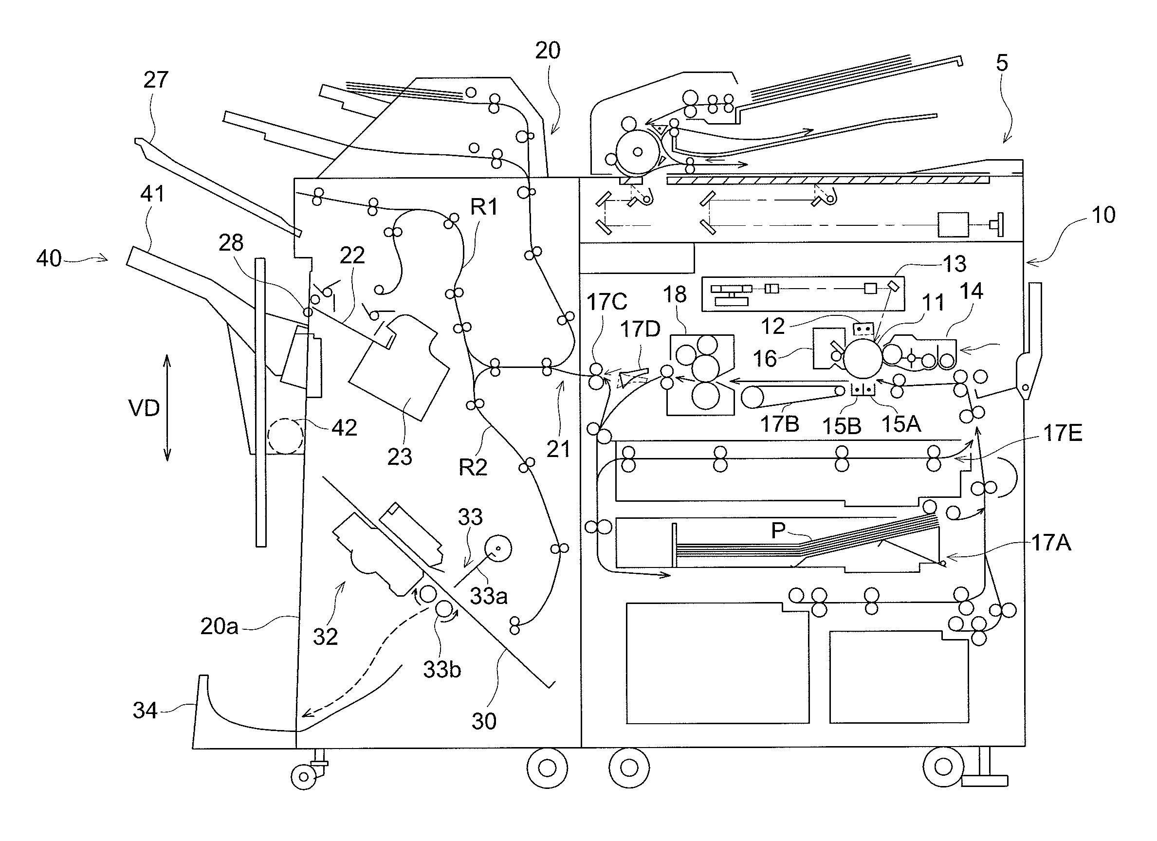
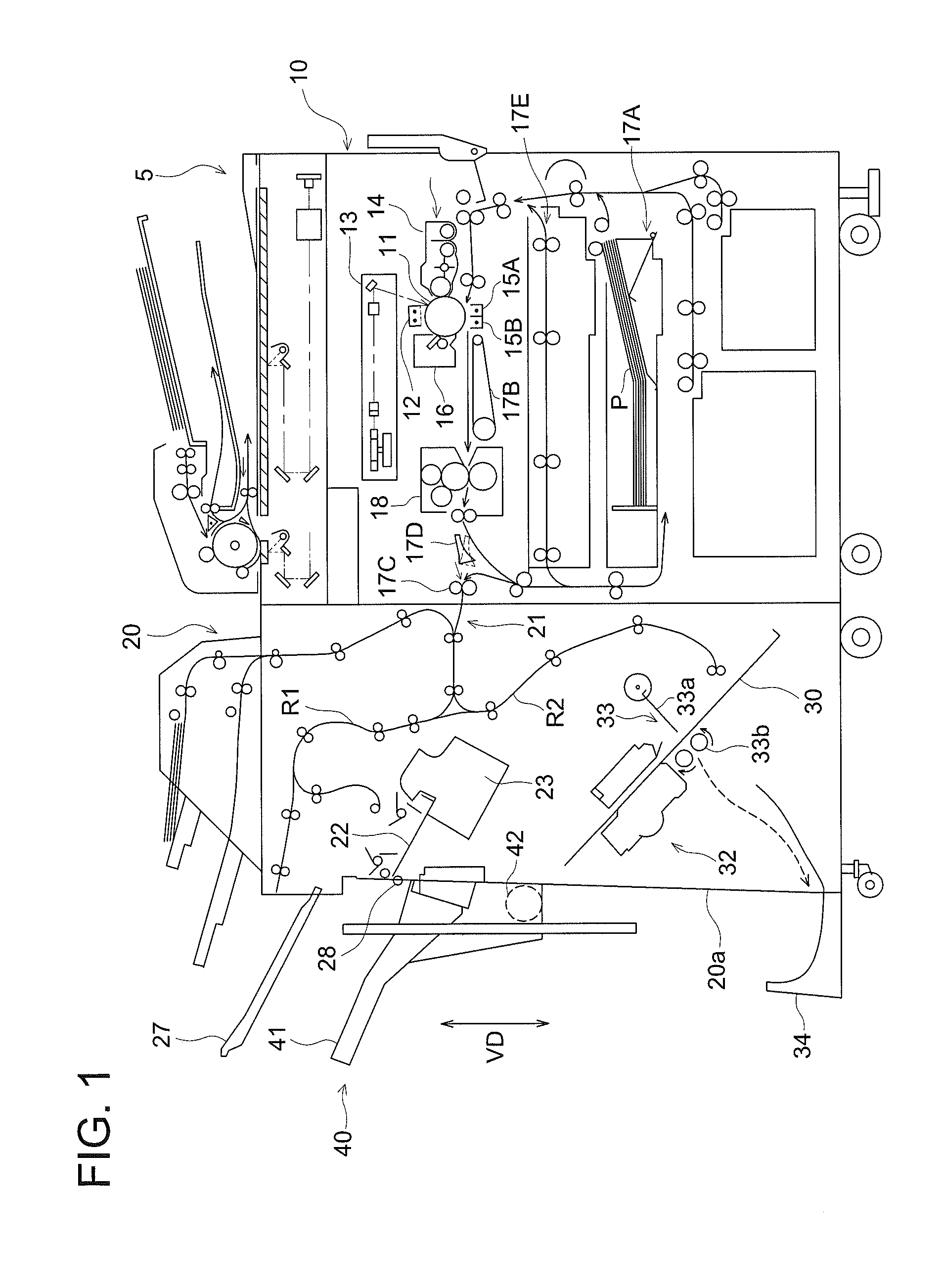
[0032]FIG. 1 is a schematic diagram representing the entire structure of an image forming system to which the sheet discharging tray device 40 of a first embodiment of the present invention is applied. The image forming system of the first embodiment is a copying machine having an image forming apparatus 10 and sheet finisher 20.

[0033]The image forming apparatus 10 forms an image on the sheet P based on the output image data. The image forming apparatus 10 includes a document reading device 5, photoreceptor 11, charging section 12, image exposing section 13, developing section 14, transferring section 15, separation section 15B, cleaning device 16 and, fixing device 18.

[0034]The document reading device 5 is placed on the upper portion of the image forming apparatus 10, and is provided with an automatic document feeding section that reads an image by moving the document. This document reading device 5 reads an image formed on the document and outputs a prescribed image signal. The im...

embodiment 2

[0121]The following describes the image forming system in the second embodiment of the present invention. The difference between the image forming system of the second embodiment and that of the first embodiment is found in the operation of the sheet discharging tray device 40 when an alignment deviation has been detected. The following mainly describes the difference. The description of the same structure as that of the first embodiment will be omitted to avoid duplication.

[0122]When an alignment deviation has been detected, the tray controller 62 changes the sheet discharge status of sheets P so that the distance between adjoining discharged sheets P will be increased as a result of change in the operation status of the middle sheet discharging tray 41. In the present embodiment, the tray controller 62 changes the distance between feeding sheets (i.e., PPM (Prints Per Minute)) per sheet as the sheet discharge status of sheets P. To put it more specifically, the tray controller 62 ...

embodiment 3

[0125]FIG. 11 is a schematic diagram schematically representing the entire structure of an image forming system to which the sheet discharging tray device of a third embodiment is applied. The difference between the image forming system of the third embodiment and that of the first embodiment is found in that an intermediate conveyance device 70 is provided between the image forming apparatus 10 and sheet finisher 20. The following mainly describes the difference. The description of the same structure as that of the first embodiment will be omitted to avoid duplication.

[0126]The major components of the intermediate conveyance device 70 include a superimposing section 71 and an intermediate conveyance controller (not illustrated).

[0127]The superimposing section 71 is structured in such a way that a plurality of sheets P conveyed from the image forming apparatus 10 are stacked one on top of another, and are conveyed to the sheet finisher 20 in one operation. To be more specific, these...


PUM


Abstract

A sheet discharging tray device includes: a discharging section from which a sheet is discharged; a discharging tray on which the sheet discharged from the discharging section is stacked sequentially; a tray drive section which drives the discharging tray in a tray shift direction that is perpendicular to a sheet discharging direction from the discharging section with reference to a sheet surface; a controller which conducts a tray shift operation that shifts a position of the discharging tray under a condition of the number of sheets stacked on the discharging tray, and a sheet detection section which detects an alignment deviation in the tray shift direction. The controller changes an operation status of the discharging tray when a tray shift operation is conducted and changes a discharging operation of a sheet to the discharging tray, based on a detected result of the sheet detection section.

Description

[0001]This application is based on Japanese Patent Application No. 2010-246235 filed on Nov. 2, 2010, which is incorporated hereinto by reference.BACKGROUND OF THE INVENTION[0002]The present invention relates to a sheet discharging tray device and an image forming system provided with the sheet discharging tray device.[0003]What is commonly known in the prior art includes an image forming system. This image forming system is provided with an image forming apparatus using the elecirophotographic process, and includes a sheet finisher for performing various forms of sheet finishing operations as required, and an intermediate conveyance device for conveyance of sheets between the image forming apparatus and sheet finisher.[0004]The image forming system of this type includes a sheet discharging tray device equipped with a sheet discharging tray for loading sheets discharged from the sheet discharging section on the final stage of the system. To discharge a great number of sheets, this s...

Claims


Application Information

Patent Timeline
Patent Type & Authority Applications(United States)
IPC IPC(8): B65H31/34
CPCB65H31/10B65H31/18B65H33/08B65H2405/351B65H2511/20B65H2801/06B65H2511/514B65H2513/51B65H2553/412B65H2701/1315B65H2511/30B65H2220/02B65H2220/01B65H2220/09
Inventor TAMADA, TAKESHISUGIMOTO, EIJIYAMAUCHI, KAZUMICHIYAMANE, HIDEO
Owner KONICA MINOLTA BUSINESS TECH INC
Why Eureka
Try Eureka