
A high-performance multi-vane hydraulic motor

A hydraulic motor, multi-blade technology, used in machines/engines, rotary or oscillating piston engines, rotary piston engines, etc., can solve problems such as poor sealing performance, low specific power, and insufficient output torque, and achieve easy processing, High specific power and compact structure

Active Publication Date: 2020-02-07
ZHEJIANG UNIV
View PDF7 Cites 0 Cited by
  • Summary
  • Abstract
  • Description
  • Claims
  • Application Information

AI Technical Summary

Problems solved by technology

This form of vane hydraulic motor is sealed by a contact line between the vane and the cylinder body, so the sealing performance is poor, the output torque is low, and there is a lot of friction between the vane, the rotor and the cylinder during rotation, resulting in the blade The overall wear of the hydraulic motor is fast, the life is short, and the efficiency is low
In addition, in order to ensure that the blades can safely enter and exit the rotor during rotation, the rotor must have a considerable diameter, which is bound to be large in size and low in specific power. Although there are double-blade hydraulic motors, since there are only two blades, the output torque fluctuates greatly , the output torque is also undersized

Method used


Image

  • A high-performance multi-vane hydraulic motor
  • A high-performance multi-vane hydraulic motor
  • A high-performance multi-vane hydraulic motor

Examples


Embodiment Construction

[0039] Reference will now be made in detail to the exemplary embodiments, examples of which are illustrated in the accompanying drawings. In the following descriptions and drawings, unless otherwise indicated, the same numerals in different drawings indicate the same or similar elements. The implementations described in the following exemplary examples do not represent all implementations consistent with the present invention. Rather, they are merely examples of arrangements consistent with aspects of the invention as recited in the appended claims. Each embodiment in this specification is described in a progressive manner.

[0040] It should be noted that all directional indications (such as up, down, left, right, front, back...) in the embodiments of the present invention are only used to explain the relationship between the components in a certain posture (as shown in the accompanying drawings). Relative positional relationship, movement conditions, etc., if the specific ...


PUM


Abstract

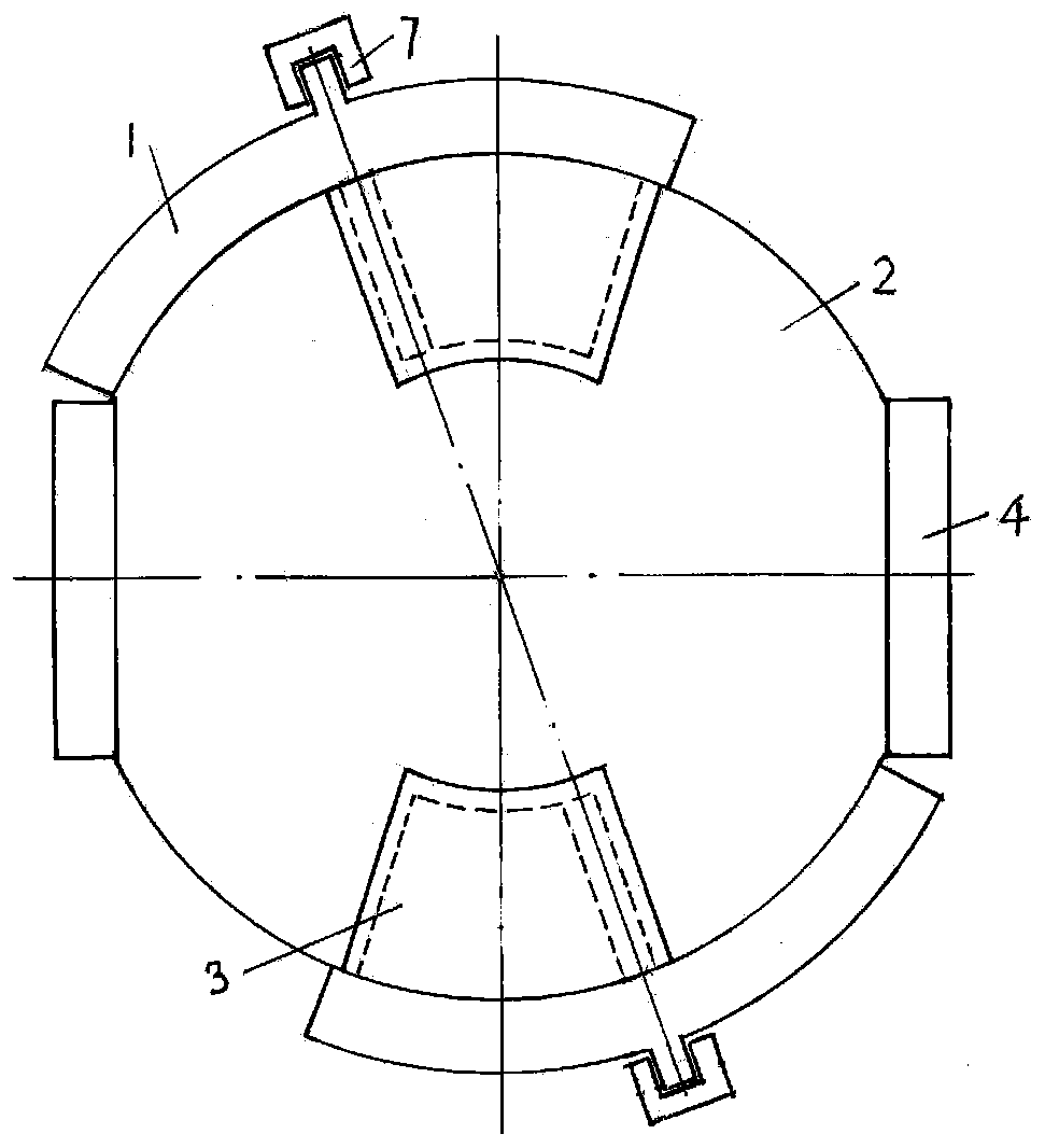
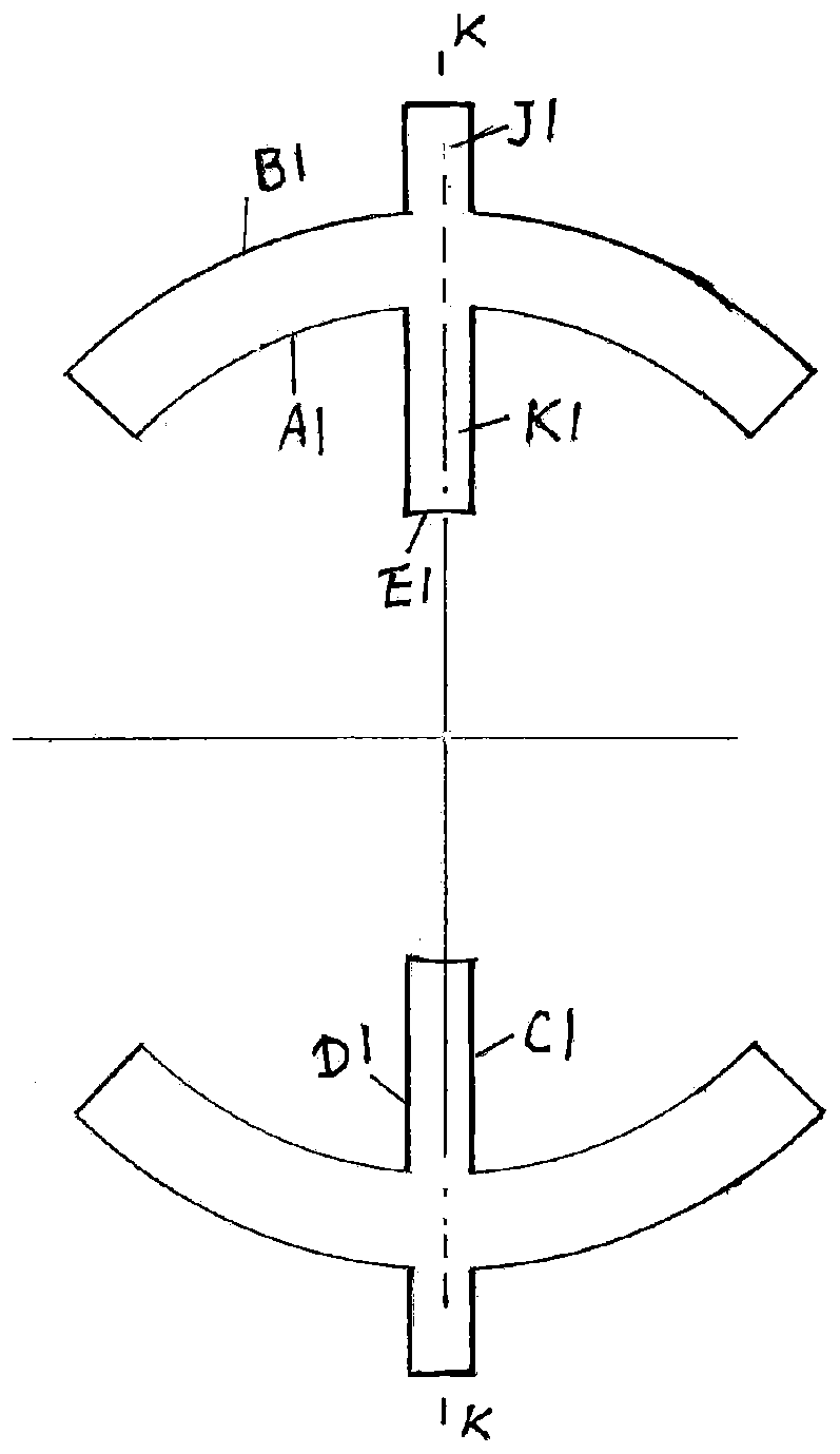
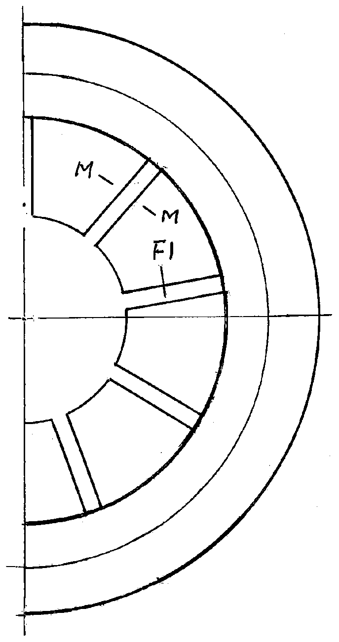
The invention provides a high-performance multi-blade hydraulic motor. The high-performance multi-blade hydraulic motor comprises a shell, a rotor, blades, oil distribution blocks and guide blocks. The outer side of the rotor is covered with the shell. At least three shifting blocks which are uniformly distributed in the circumferential direction are arranged in the shell. A chute is formed between every two shifting blocks. A ring groove is formed in the centring position of the side wall of the rotor. Positioning grooves with the same number as the shifting blocks are uniformly formed in thering groove in the circumferential direction. A blade is mounted on each positioning groove. A cavity is formed among every two adjacent blades, the surface of the ring groove and the inner wall of the shell. The blades are inserted into the corresponding chutes. One shifting block is arranged in each cavity. Each cavity is partitioned into a first cavity body and a second cavity body by the corresponding shifting block. Both ends of the rotor are correspondingly connected with the oil distribution blocks, A convex ring J1 of the outer wall of the shell is arranged in guide grooves of the guide blocks. The axis of the rotor and the axis of the shell do not coincide. The volume of a high-pressure oil driving chamber periodically increases and decreases, so that the rotor is driven to rotate, and power output is realized.

Description

technical field [0001] The invention relates to a multi-vane motor, in particular to a high-performance multi-vane hydraulic motor. Background technique [0002] The structure of the existing vane hydraulic motor is that the rotor is eccentrically placed in the oil cylinder body, and the blades are placed in the rotor radially or at a certain angle with the rotor radius. Form a sealed cavity. This form of vane hydraulic motor is sealed by a contact line between the vane and the cylinder body, so the sealing performance is poor, the output torque is low, and there is a lot of friction between the vane, the rotor and the cylinder during rotation, resulting in the blade The overall wear of the hydraulic motor is fast, the life is short, and the efficiency is low. In addition, in order to ensure that the blades can safely enter and exit the rotor during rotation, the rotor must have a considerable diameter, which is bound to be large in size and low in specific power. Although...

Claims


Application Information

Patent Timeline
Patent Type & Authority Patents(China)
IPC IPC(8): F03C2/30
CPCF03C2/304
Inventor 陈行
Owner ZHEJIANG UNIV
Learn More