Radar system and method for a synthetic aperture radar

a synthetic aperture radar and radar system technology, applied in the direction of reradiation, measurement devices, instruments, etc., can solve the problems of inability to use at small platforms, and inability to meet the requirements of vhf frequency rang

Active Publication Date: 2012-05-03
SAAB AB
View PDF28 Cites 19 Cited by
  • Summary
  • Abstract
  • Description
  • Claims
  • Application Information

AI Technical Summary

Benefits of technology

[0017]A further advantage is achieved if the Voltage Standing Wave Ratio (VSWR) of the radar system is arranged to be reduced by insertion of VSWR reducing means in the radar system between the transmitter and the antennas, by implementing dependent claims 2 and 13.

Problems solved by technology

Several important SAR applications however, require small platforms such as small manned, fixed wing or rotary wing aircrafts or tactical Unmanned Aerial Vehicles (UAVs), for which antennas with the stated type of dimensions are too large.
The antenna dimensions required for this solution at VHF frequency range are however of the order of several meters and not feasible to use at small platforms.

Method used


Image

  • Radar system and method for a synthetic aperture radar
  • Radar system and method for a synthetic aperture radar
  • Radar system and method for a synthetic aperture radar

Examples


Embodiment Construction

[0031]The invention will now be described in detail with reference to the drawings.

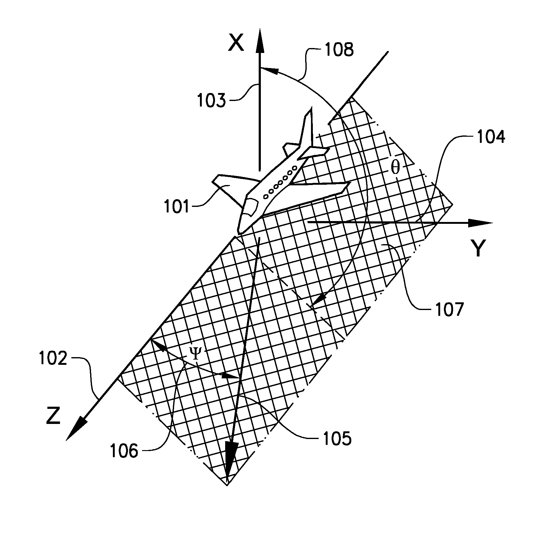
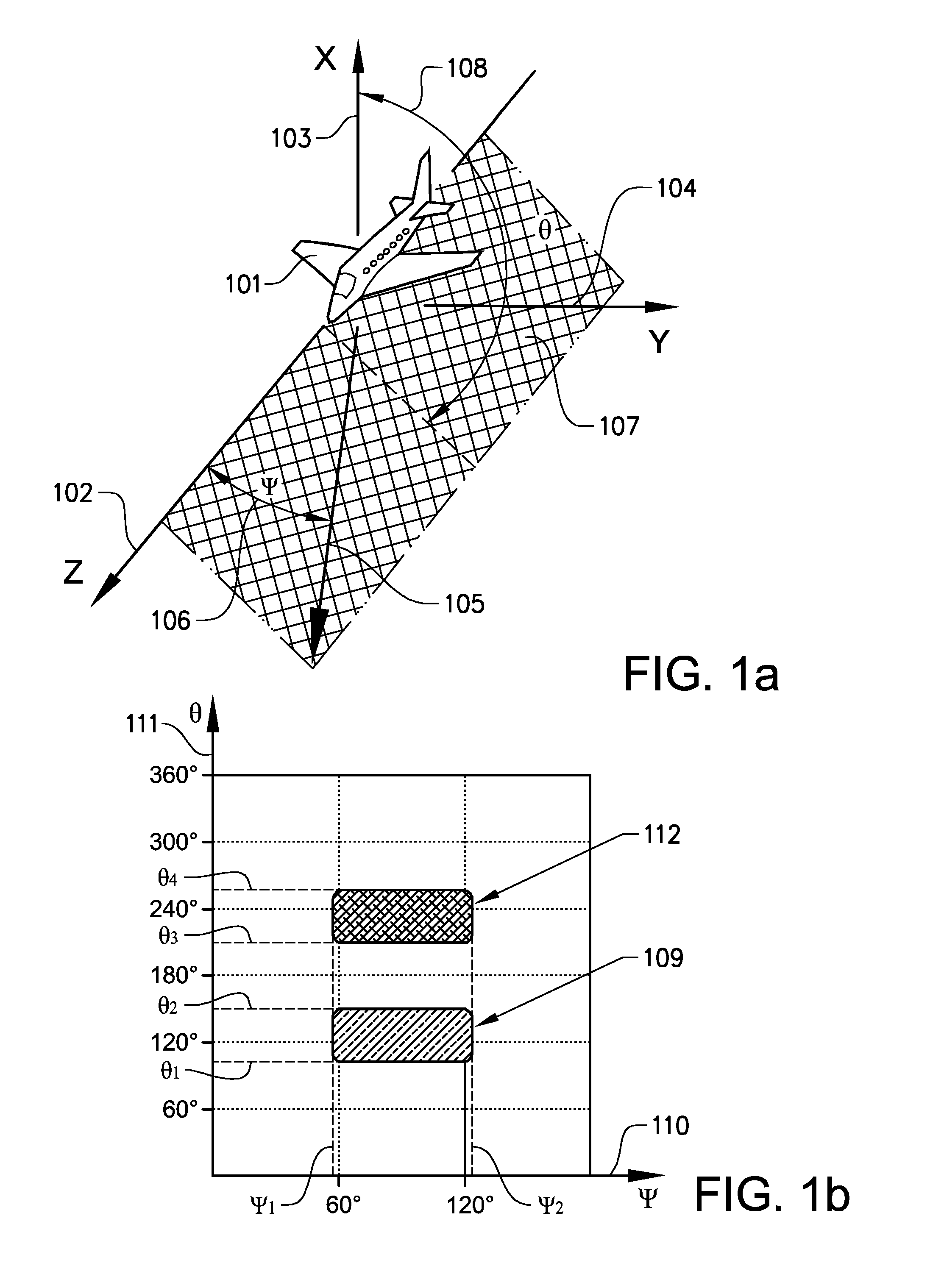
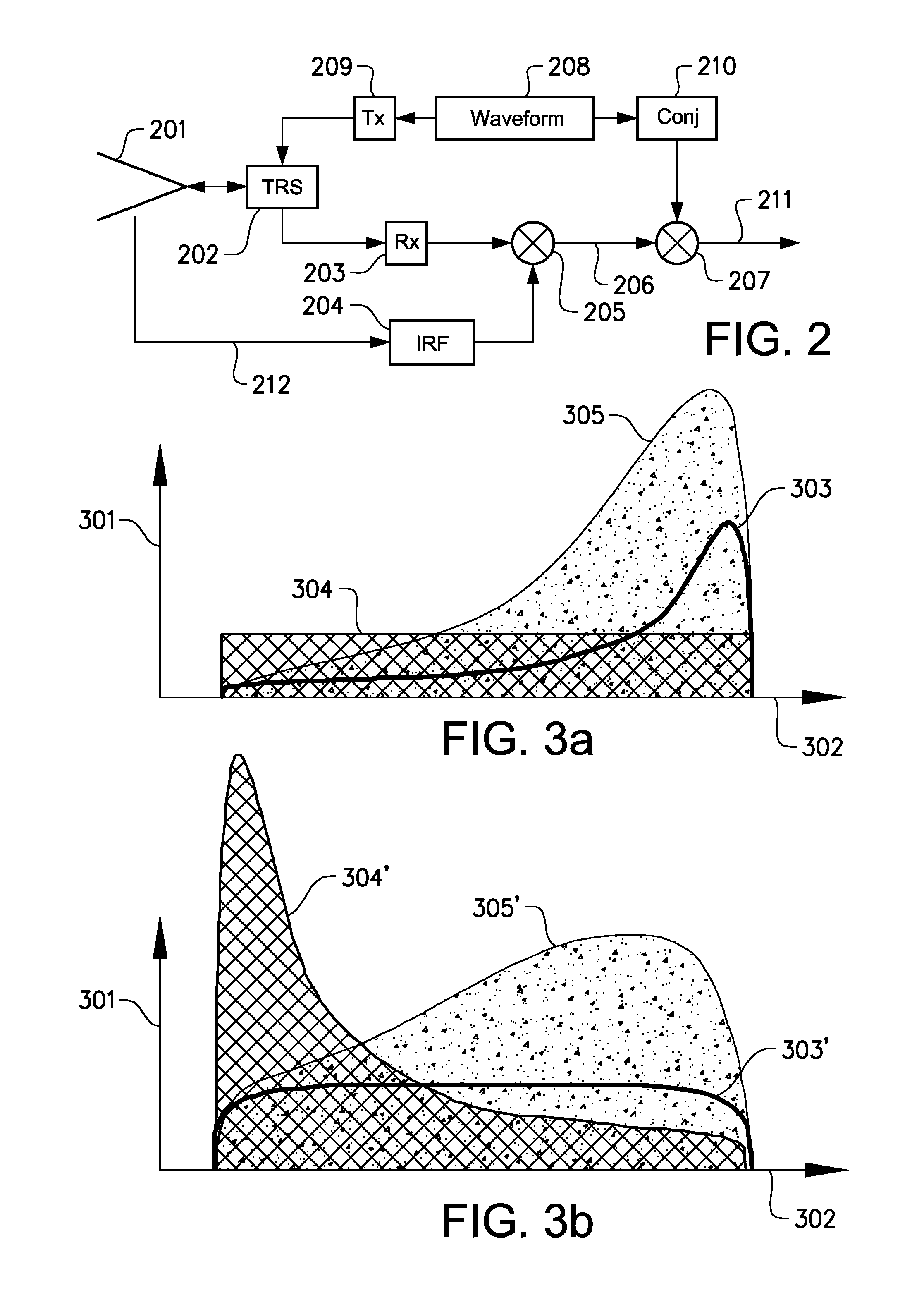
[0032]The invention addresses a new radar system and method for radar imaging of a surrounding ground surface from a moving platform, preferably a fixed wing or rotary wing aircraft or UAV. The imaging system is typically a Synthetic Aperture Radar (SAR) that will perform its task by a radar system comprising an arrangement of at least one transmitter, two receivers, two antennas and signal processing means located on the platform, which platform is moving over ground and arranged to transmit a known signal shape and receive signals reflected from the ground. The two antennas included in the radar system is henceforth referred to as the antenna arrangement. The received signals are used to produce the SAR image of the ground. A new technology has been devised in which the radar system performs the imaging task at meter wavelengths rather than (as is the normal case) at microwave frequencies. The choic...


PUM


Abstract

A radar system for a synthetic aperture radar including an arrangement of at least one transmitter, two receivers, two antennas and signal processing means located on a platform. The platform is arranged to move over ground and arranged to transmit a known signal shape and receive signals reflected from the ground. The received signals are used to produce a synthetic aperture radar image of the ground. The synthetic aperture radar image includes a number of resolution cells. The radar system is further arranged to operate in a frequency band with a center frequency and with a wide bandwidth of at least one octave. A first antenna and a second antenna have a length of less than half the wavelength of the center frequency. The radar system is further arranged for: a radar system transfer function to be flat over the frequency band and one-sided beam forming with wideband antenna gain. Also a corresponding method.

Description

TECHNICAL FIELD[0001]The present invention relates to the field of radar systems and antennas for Synthetic Aperture Radar (SAR).BACKGROUND ART[0002]SAR as such is a known technique, by which it is possible with a radar system mounted on a moving platform, normally an aircraft or a satellite, to obtain high resolution images of the ground. Radar responses from the ground are stored during some interval of the flight of the platform. The SAR image is obtained by signal processing in ways similar to computer tomography. Image resolution is determined by the angular span of viewing angles of the imaged ground, as well as the wavelength used and the distance between the radar and the ground. This means that the actual resolution of the radar antenna is of no importance for the resolution of the obtained image.[0003]In SAR there is no fundamental requirement on resolution of the radar antenna, which consequently is not required to be directive. Thus it is possible to use unconventional r...

Claims


Application Information

Patent Timeline
Patent Type & Authority Applications(United States)
IPC IPC(8): G01S13/90
CPCG01S13/90G01S13/28G01S13/0209G01S2013/9041G01S13/9041
Inventor ANDERSSON, LARS-GUNNARHELLSTEN, HANS
Owner SAAB AB
Why Eureka
Try Eureka