High-frequency coaxial cable

a coaxial cable and high-frequency technology, applied in the direction of power cables, cables, insulated conductors, etc., can solve the problems of not being able to change the conductor loss, the voltage standing wave ratio of the cable is deteriorated, and the dielectric loss is not reduced, so as to reduce the voltage standing wave ratio and reduce the attenuation amount

Inactive Publication Date: 2009-06-18
HITACHI METALS LTD
View PDF0 Cites 15 Cited by
  • Summary
  • Abstract
  • Description
  • Claims
  • Application Information

AI Technical Summary

Benefits of technology

[0025]It is an object of the invention to solve the above mentioned problem and to provide a high-frequency coaxial cable having a reduced voltage standing wave ratio and a reduced attenuation amount.

Problems solved by technology

It is not possible to change the conductor loss, since the conductor loss is determined by a configuration of the high-frequency coaxial cable 41.
Furthermore, since a diameter of the foamed resin insulation layer is increased toward the outside when foaming, a clearance is generated between the conductor and the foamed resin insulation layer, so that the voltage standing wave ratio of the cable is deteriorated.
However, since the dielectric tangent of the low-density polyethylene is larger than that of the high-density polyethylene, the dielectric loss is not reduced, even though the foaming degree is increased.
Therefore, it is not possible to reduce the attenuation amount of the high-frequency coaxial cable.
Furthermore, the voltage standing wave ratio is deteriorated, since no inner solid layer is provided.
Furthermore, when the thickness of the outer solid layer is 0.2 mm or more, it is not possible to engage an outer conductor enough with the outer solid layer, since the outer solid layer is hard.
Furthermore, the voltage standing wave ratio means an error when applying a current to the high-frequency coaxial cable.
This error is generated by a generation of the interconnected cell or the infiltration of the water.

Method used


Image

  • High-frequency coaxial cable
  • High-frequency coaxial cable
  • High-frequency coaxial cable

Examples


embodiment

[0076]

TABLE 1EmbodimentEmbodimentEmbodimentEmbodimentEmbodimentComparativeMaterial12345Example 1CompositionFoamed resinHDPE 6944N(1)858585858585InsulationLDPE B028(2)151515151515layernucleation0.0050.0050.0050.0050.0050.005agent ADCAOuter solid6944N100——100100—layer2500(3)—100————2070(4)——100———130J(5)—————100210JZ(6)——————232J(7)——————Property ofDensity (g / cm3)0.9650.9630.9620.9650.9650.962outer solidMFR (g / 10 min)8.05.08.08.08.012.0layertan δ (2 GHz × 10−4)0.60.910.60.60.95Thickness (mm)0.150.20.170.10.20.05Melting fracture10451510102tension (190° C. · mN)Property ofFoaming degree (%)767476767473Foamed resinInfiltration of the waterNoNoNoNoNoYesinsulationlayerInner solidPresence of the inner solid layerYesYesYesYesYesYeslayerProperty ofVSWR1.051.051.051.051.051.1cable(passed at 1.1 or less)Attenuation amount at 2.2 GHzPassedPassedPassedPassedPassedFailed(passed at 6.5 dB / 100 m or less)ComparativeComparativeComparativeComparativeComparativeMaterialExample 2Example 3Example 4Example...


PUM

PropertyMeasurementUnit
thicknessaaaaaaaaaa
melt flow rateaaaaaaaaaa
densityaaaaaaaaaa

Abstract

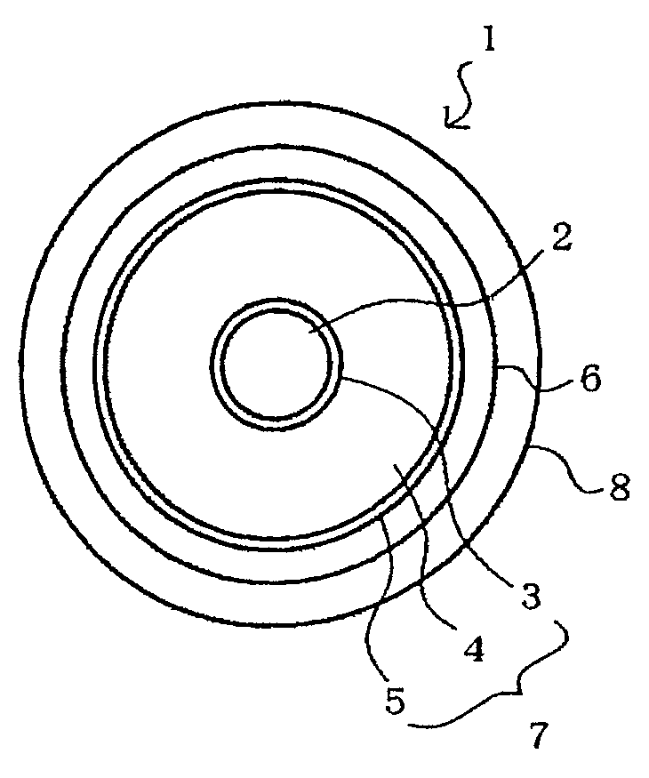
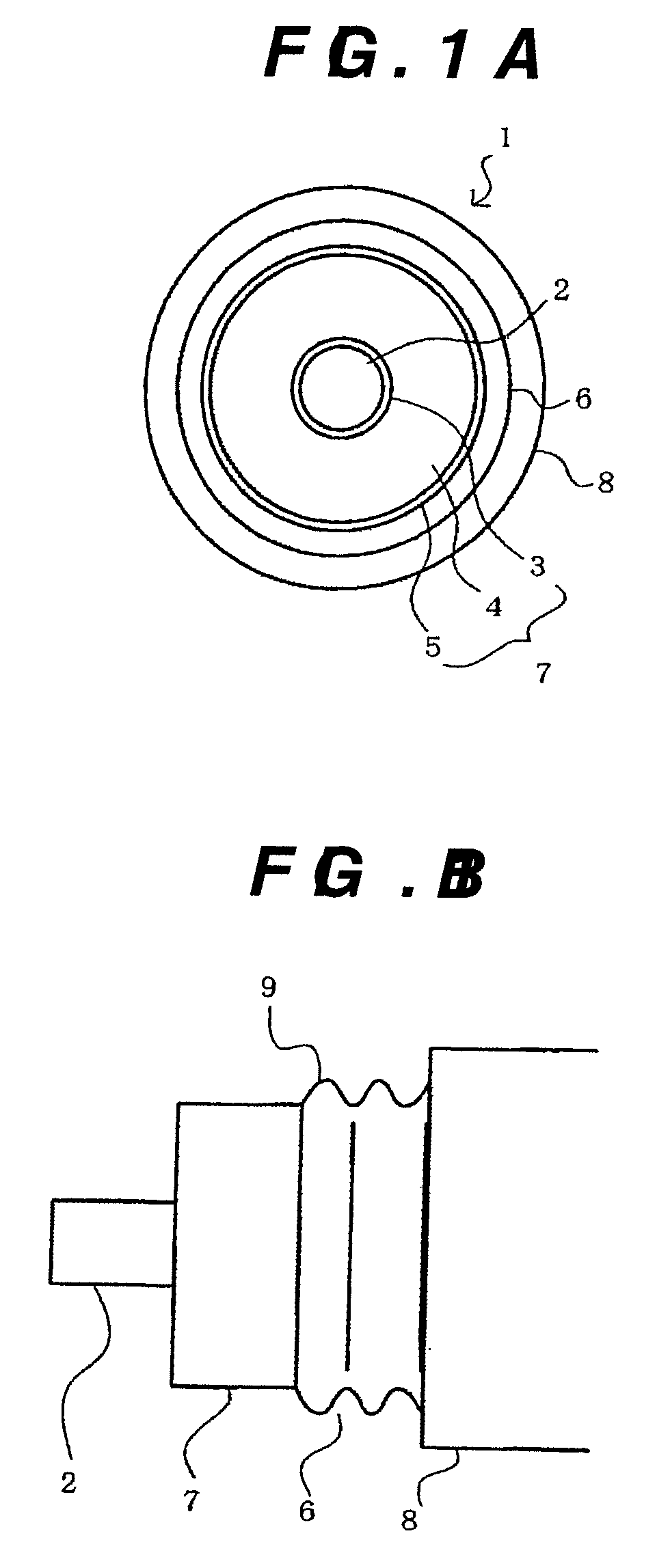
In a high-frequency coaxial cable (1), an internal solid layer (3), an insulation layer (4) made of a foam resin, an external solid layer (5), and an external conductor (6) are provided on the periphery of an internal conductor (2) in this order. The external solid layer (5) has a dielectric dissipation factor of 1.0×10⁻⁴ or less at 2 GHz. Thereby, the voltage standing-wave ratio and the attenuation of the high-frequency coaxial cable (1) are reduced.

Description

BACKGROUND OF THE INVENTION[0001]1. Field of the Invention[0002]The present invention relates to a high-frequency coaxial cable having a reduced voltage standing wave ratio and a reduced attenuation amount. The present application is based on Japanese Patent Application Nos. 2006-170134 and 2007-151079, the entire contents of which are incorporated herein by reference.[0003]2. Related Art[0004]A high-frequency coaxial cable 41 used in mobile communication facilities for relaying mobile phone lines and microwave communication facilities for relaying television transmission lines comprises an insulation layer 47 comprising three layers composed of an inner solid layer 43, a foamed resin insulation layer 44 and an outer solid layer 45 provided between an inner conductor 42 and an outer conductor 46, and a jacket 48 on an outer periphery of the outer conductor 46 as shown in FIGS. 4A and 4B.[0005]In this high-frequency coaxial cable 41, a usable frequency tends to be high for the purpos...

Claims


Application Information

Patent Timeline
Patent Type & Authority Applications(United States)
IPC IPC(8): H01B11/18
CPCC08J9/04C08J2203/04H01B13/067C08J2323/06H01B11/1839C08J2203/06
Inventor ABE, MASAHIROSUZUKI, HIDEYUKISHIBATA, TOMOKAZUKUZIRAOKA, MASATSUGU
Owner HITACHI METALS LTD
Why Eureka
Try Eureka