Optical fingerprint recognition system

Active Publication Date: 2012-05-03
GINGY TECH
View PDF7 Cites 35 Cited by
  • Summary
  • Abstract
  • Description
  • Claims
  • Application Information

AI Technical Summary

Benefits of technology

[0007]Accordingly, the present invention is an optical fingerprint recognition system, which is capable of improving the recognition rate and simplifying the assembling process.
[0009]The present invention has the efficacy that the micro-structures make the incident light ray to be uniformly distributed in the finger board, so as to facilitate the light ray incident on the finger to be uniform and intensive, thus effectively improving the recognition rate.

Problems solved by technology

As a result, the assembling is difficult, and the assembling cost is high, and thus the economical effect is poor.

Method used


Image

  • Optical fingerprint recognition system
  • Optical fingerprint recognition system
  • Optical fingerprint recognition system

Examples


second embodiment

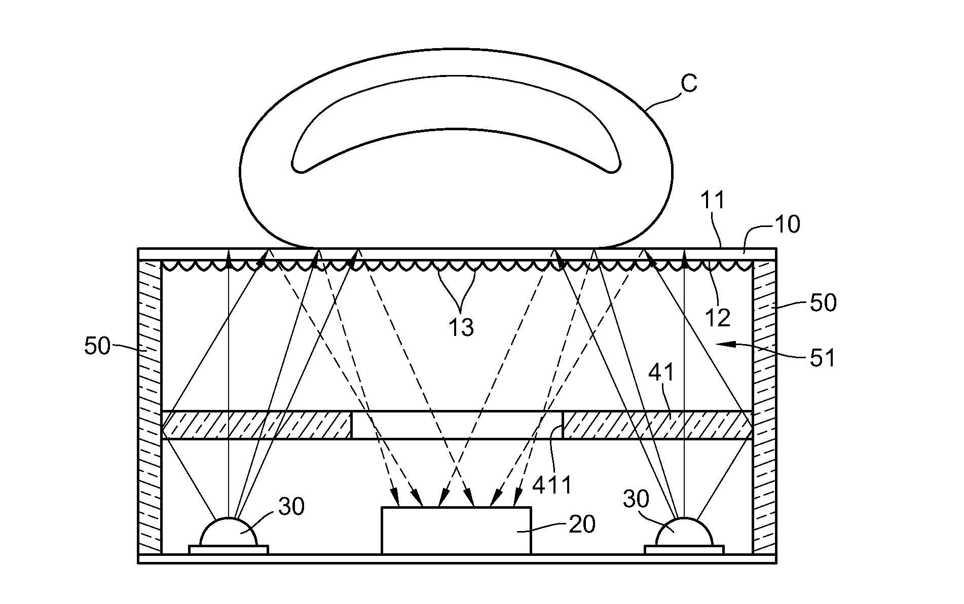
[0031]FIG. 4 is a schematic view of an optical fingerprint recognition system according to the present invention. The optical fingerprint recognition system further comprises an optical element. The optical element is a transmissive light diffusion plate 41, and the light diffusion plate 41 is disposed between the finger board 10 and the image capturing element 20. The light diffusion plate 41 has an opening 411, and the opening 411 is opposite to the image capturing element 20.

[0032]When the light emitting element 30 emits a light ray towards the light diffusion plate 41, the light ray is converted into a surface light source by the light diffusion plate 41, and the surface light source uniformly overlaps the entire area of the finger board 10, so as to ensure that the surface light source covers the whole surface of the finger board 10. The transmission path of the surface light source is changed by the micro-structures 13 and scattering is generated, thus enhancing the effect of ...

fourth embodiment

[0037]FIG. 6 is a schematic view of an optical fingerprint recognition system according to the present invention. The optical fingerprint recognition system further comprises at least two light guide elements 50, which are disposed at two opposite sides of the optical element respectively. In this embodiment, the optical element is illustrated with a light diffusion plate 41 as an example, but the present invention is not limited thereto. Next, the finger board 10 is disposed on the top of the light guide elements 50. Thus, the finger board 10, the light diffusion plate 41, and the light guide elements 50 surround and define a cavity 51. When the finger C is placed on the finger board 10, the light emitting element 30 emits a light ray towards the light diffusion plate 41, and due to the design of the structure of the light diffusion plate 41 and the light guide elements 50, the light ray forms a uniform light field in the cavity 51, such that the finger board 10 and the plurality o...


PUM


Abstract

An optical fingerprint recognition system has a finger board. The finger board has a plurality of micro-structures, and a plate face of the finger board is to be in contact with a finger, and the other plate face of the finger board has an image capturing element and at least one light emitting element disposed thereon. The image capturing element and the light emitting element are separated from the finger board for a distance. When the light emitting element emits a light ray towards the finger board, the light ray is guided by the plurality of micro-structures to be uniformly distributed in the finger board, so as to facilitate the image capturing element to capture the light ray applied on the finger, thus improving the recognition rate of the fingerprint.

Description

CROSS-REFERENCE TO RELATED APPLICATIONS[0001]This non-provisional application claims priority under 35 U.S.C. §119(a) on Patent Application No(s). 20-2010-0011107 filed in Korea on Oct. 28, 2010, the entire contents of which are hereby incorporated by reference.BACKGROUND OF THE INVENTION[0002]1. Field of Invention[0003]The present invention relates to a fingerprint recognition system, and more particularly to an optical fingerprint recognition system having a finger board with a plurality of micro-structures.[0004]2. Related Art[0005]U.S. Pat. No. 5,177,802 mainly includes an image capturing element, a light guide plate disposed above the image capturing element, and two light emitting elements disposed at two sides of the light guide plate. When the light emitting elements emit light, the light guide plate guides the incident light to be projected on a finger and then reflected to the image capturing element according to total reflection principle, thus achieving an effect of fing...

Claims


Application Information

Patent Timeline
IPC IPC(8): H04N7/18
CPCG06K9/00046G06V40/1324G06V10/10
Inventor WU, CHIEN HSINGWU, JEN CHIEH
Owner GINGY TECH
Why Eureka
Try Eureka