Moving Image Pickup Apparatus, Method For Observing Moving Image, Moving Image Observing Program, And Computer-Readable Recording Medium

Active Publication Date: 2012-05-03
KEYENCE
View PDF3 Cites 6 Cited by
  • Summary
  • Abstract
  • Description
  • Claims
  • Application Information

AI Technical Summary

Benefits of technology

[0010]In order to attain the above object, according to one embodiment of a moving image 
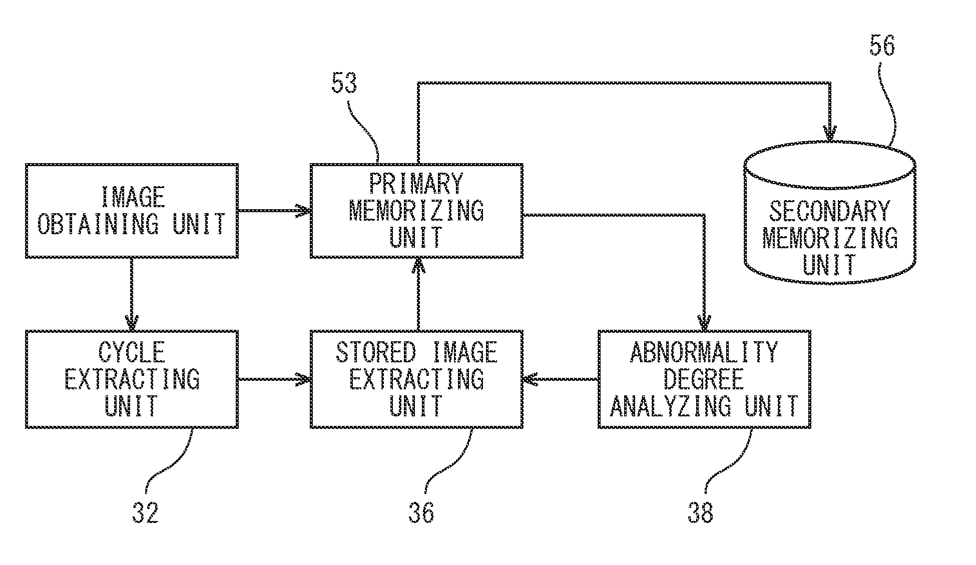
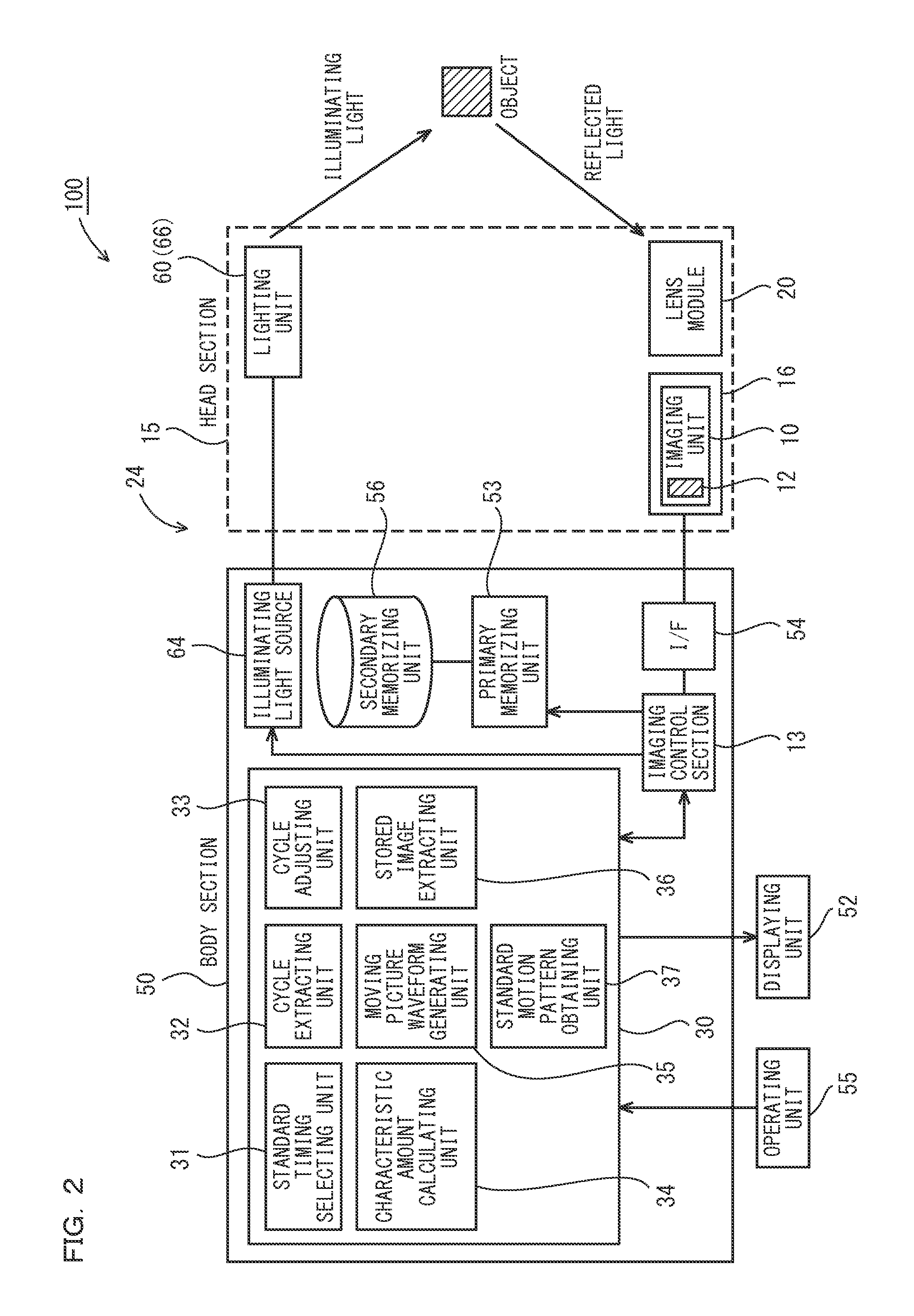
pickup apparatus in the present invention, the moving image pickup apparatus to pick up a moving image of one or more objects as an imaging target includes an image obtaining unit for obtaining an input moving image composed of a plurality of frames containing a scene of the object making a periodic motion, a representative image selecting unit for selecting a representative image representing a cycle, a standard timing selecting unit 31 for selecting a standard timing based on the representative image, in order to divide the input moving image obtained by the image obtaining unit with respect to each cycle, and a cycle extracting unit 32 for dividing the input moving image with respect to each cycle, based on the standard timing selected by the standard timing selecting unit 31. Thus, since the obtained input moving image can be periodically divided, an analyzing operation of the moving image by the user can be considerably reduced, and in analyzing the moving image containing a great amount of image frames with a high-speed camera especially, the analysis can be effectively made.
[0011]In addition, according to another embodiment of the moving image pickup apparatus, the representative image selecting unit can be configured to automatically select the representative image. Thus, since the input moving image can be periodically divided using the automatically selected representative image as an image trigger, the analyzing operation of the moving image by the user can be considerably reduced.
[0016]In addition, according to yet another embodiment of the moving image pickup apparatus, it may further include a characteristic amount calculating unit 34 for calculating a characteristic amount of each frame or each frame group from the input moving image obtained by the image obtaining unit, based on the representative image, and a moving picture waveform generating unit 35 for generating a moving picture waveform, based on the characteristic amount calculated by the characteristic amount calculating unit 34, in which the standard timing selecting unit 31 can select the standard timing, based on the moving picture waveform. Thus, a quantitative evaluation can be made based on the moving picture waveform, and the division can be easily made with respect to each cycle using the moving picture waveform.
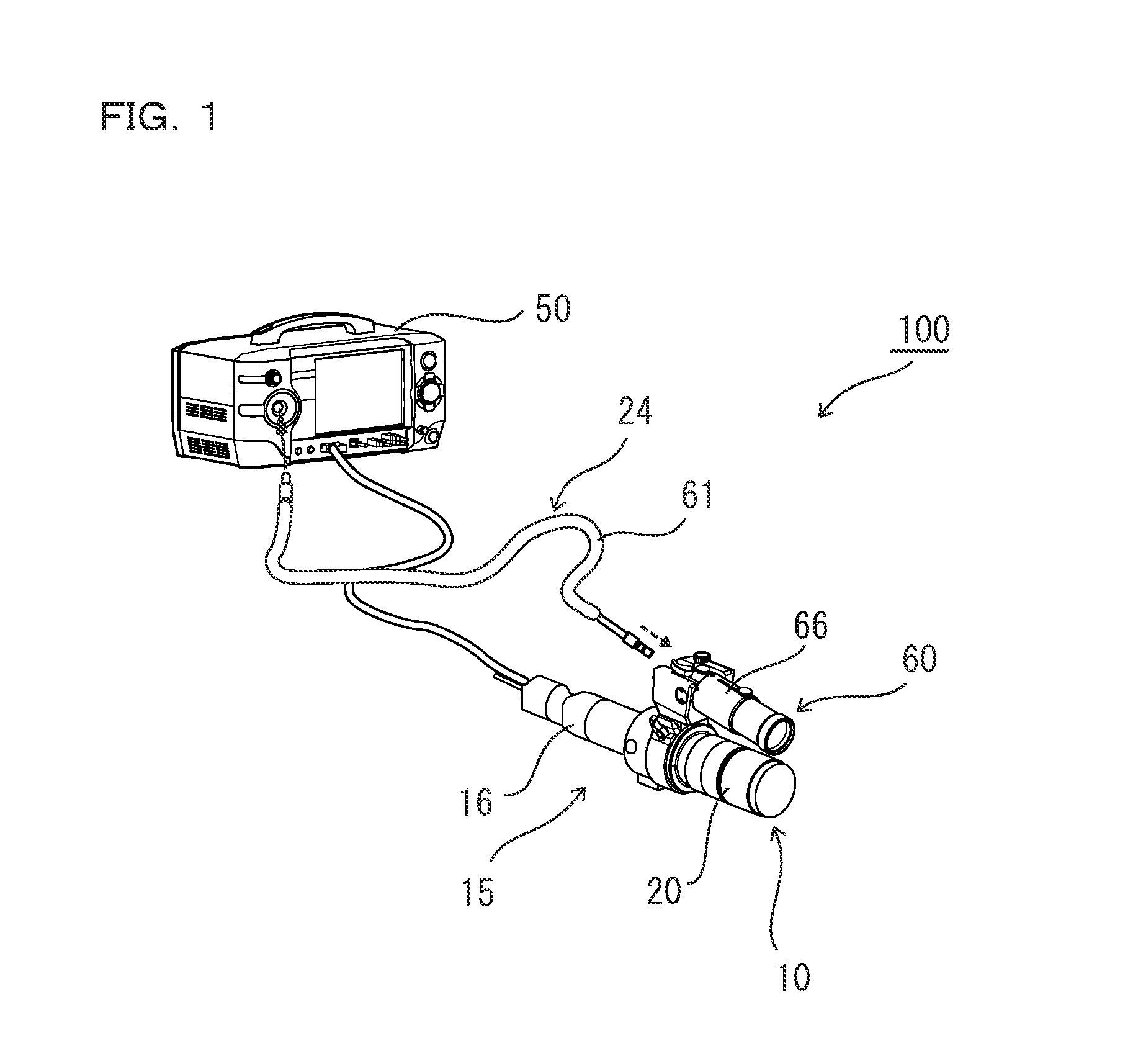
[0026]In addition, according to yet another embodiment of the moving image pickup apparatus, the image obtaining unit is an imaging unit 10 capable of picking up the input moving image of the object at an imaging cycle of not more than 1 / 25 second. Thus, the analysis can be effectively made in analyzing the moving image containing the great amount of image frames.
[0027]In addition, according to one embodiment of a method for observing a moving image of one or more objects as an imaging target, it includes the steps of obtaining an input moving image composed of a plurality of frames containing a scene of the object making a periodic motion, calculating a characteristic amount of each frame or each frame group from the obtained input moving image by a characteristic amount calculating unit 34, generating a moving picture waveform, based on the calculated characteristic amount, obtaining a standard timing to determine a cycle of the moving picture waveform by a standard timing selecting unit 31, based on the moving picture waveform, and dividing the input moving image with respect to each cycle, based on the standard timing. Thus, each cycle can be synchronized by the standard timing, and the division can be made with respect to each cycle without the synchronous input. In addition, the quantitative evaluation can be made based on the moving picture waveform, and the division can be easily made with respect to each cycle using the moving picture waveform.
[0028]In addition, according to one embodiment of a moving image observing program to observe a moving image of one or more objects as an imaging target, it causes a computer to implement the functions of obtaining an input moving image composed of a plurality of frames containing a scene of the object making a periodic motion, calculating a characteristic amount of each frame or each frame group from the obtained input moving image, generating a moving picture waveform, based on the calculated characteristic amount, selecting a standard timing to determine a cycle of the moving picture waveform by comparing the moving picture waveform with a predetermined threshold value, and dividing the input moving image with respect to each cycle, based on the selected standard timing to be executed in a computer. Thus, each cycle can be synchronized by the standard timing, and the division can be made with respect to each cycle without the synchronous input. In addition, the quantitative evaluation can be made based on the moving picture waveform, and the division can be easily made with respect to each cycle using the moving picture waveform.

Problems solved by technology

Regarding the moving image picked up by the high-speed imaging apparatus, as the imaging frame rate increases, a playback time becomes extremely long compared to the imaging time, so that it is difficult to find out a desired picked-up image from enormous frame image data.
Especially, as the high-speed camera is increased in speed, and the frame rate becomes high, that is, as the number of picked-up images per unit time increases, a moving image data amount to be analyzed becomes enormous, and the problem becomes more serious.
In addition, it is not easy to analyze an imaging target object contained in the image.
In addition, when the synchronization signal cannot be obtained, or a method to obtain it is not known, the above method cannot be used.

Method used


Image

  • Moving Image Pickup Apparatus, Method For Observing Moving Image, Moving Image Observing Program, And Computer-Readable Recording Medium
  • Moving Image Pickup Apparatus, Method For Observing Moving Image, Moving Image Observing Program, And Computer-Readable Recording Medium
  • Moving Image Pickup Apparatus, Method For Observing Moving Image, Moving Image Observing Program, And Computer-Readable Recording Medium

Examples


Embodiment Construction

[0052]Hereinafter, an embodiment of the present invention will be described with reference to the drawings. Here, it is to be noted that the embodiment shown below only illustrates a moving image pickup apparatus, a method for observing a moving image, a moving image observing program, and a computer-readable recording medium to embody a technological thought of the present invention, and the present invention is not limited to the following moving image pickup apparatus, method for observing the moving image, moving image observing program, and computer-readable recording medium. In addition, this specification does not specify a member shown in the claims to a member in the embodiment. Especially, a dimension, material, shape, its relative arrangement, and the like of a component disclosed in the embodiment do not limit a range of the present invention only to themselves, and they are just an example unless otherwise noted. In addition, a size of the member, its positional relatio...


PUM


Abstract

A moving image is divided with imaging timing aligned without using a synchronous input. A moving image pickup apparatus to pick up a moving image of one or more objects as an imaging target includes an image obtaining unit for obtaining an input moving image composed of a plurality of frames containing a scene of the object making a periodic motion, a representative image selecting unit for selecting a representative image representing a cycle, a standard timing selecting unit for selecting a standard timing based on the representative image, in order to divide the input moving image obtained by the image obtaining unit with respect to each cycle, and a cycle extracting unit for dividing the input moving image with respect to each cycle, based on the standard timing selected by the standard timing selecting unit.

Description

CROSS-REFERENCE TO RELATED APPLICATIONS[0001]The present application claims foreign priority based on Japanese Patent Application No. 2010-244723, filed Oct. 29, 2010, No. 2010-244724, filed Oct. 29, 2010, and No. 2010-244725, filed Oct. 29, 2010, the contents of which is incorporated herein by reference.BACKGROUND OF THE INVENTION[0002](1) Field of the Invention[0003]The present invention relates to a moving image pickup apparatus which can pick up an image at a high frame rate such as a high-speed imaging camera, a method for observing a moving image, a moving image observing program, and a computer-readable recording medium.[0004](2) Description of the Related Art[0005]In order to photograph a change of an object, a high-speed imaging camera is used to serially pick up an image at a high frame rate. This apparatus displays frame image data picked up by an imaging unit at a predetermined imaging frame rate, on a display unit at a frame rate different from that at the time of imagi...

Claims


Application Information

Patent Timeline
IPC IPC(8): G06K9/46H04N5/228G06V10/764
CPCG01N21/8851G01N2021/889G03B39/00H04N5/3454G06K9/00718G06K9/6284G06V20/41G06V10/764H04N25/443G06F18/2433G05B2219/24097G05B2219/31447G05B2219/37572G05B19/0423
Inventor KANG, WOOBUM
Owner KEYENCE
Why Eureka
Try Eureka