Optical Angle-Measuring Device

a technology of optical angle measurement and measuring device, which is applied in the direction of measurement device, sensor output conversion, instruments, etc., can solve the problems that the scanning optics of the optical angle measurement device based on interferential scanning principles have only small mounting tolerances, and cannot be used universally for different graduation radii to be scanned, so as to achieve the effect of improving mounting tolerance and high resolution

Active Publication Date: 2012-05-03
DR JOHANNES HEIDENHAIN GMBH
View PDF2 Cites 14 Cited by
  • Summary
  • Abstract
  • Description
  • Claims
  • Application Information

AI Technical Summary

Benefits of technology

[0004]Example embodiments of the present invention provide an optical angle-measuring device having high resolution and improved mounting tolerances which is usable universally in conjunction with different graduation radii of the scanned measuring graduation and in various measuring applications, without necessitating significant adjustments of the scanning optics.
[0006]For example, the combined first and second radial-circular gratings may unite at least an azimuthal, optical, deviating effect with the optical effect of a radial, annularly curved cylindrical lens.
[0022]As further advantages of the optical angle-measuring device described herein, it should be mentioned that, besides having a possible high resolution, at the same time, it additionally has improved mounting tolerances for the graduated disk, accompanied by a relatively large scanning area on the part of the measuring graduation.

Problems solved by technology

For the most part, high-resolution optical angle-measuring devices based on interferential scanning principles have only small mounting tolerances for the graduated disk having the measuring graduation disposed on it.
Therefore, the problem results that the corresponding scanning optics of the optical angle-measuring device accordingly cannot be used universally for different graduation radii to be scanned, nor universally for various measuring applications.

Method used


Image

  • Optical Angle-Measuring Device
  • Optical Angle-Measuring Device
  • Optical Angle-Measuring Device

Examples


Embodiment Construction

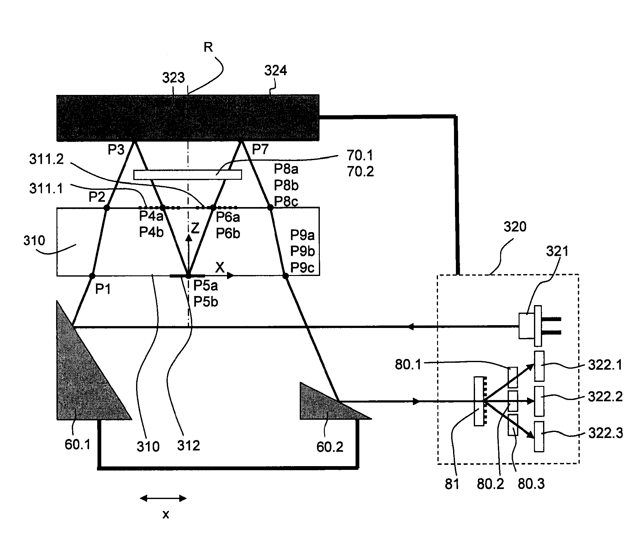
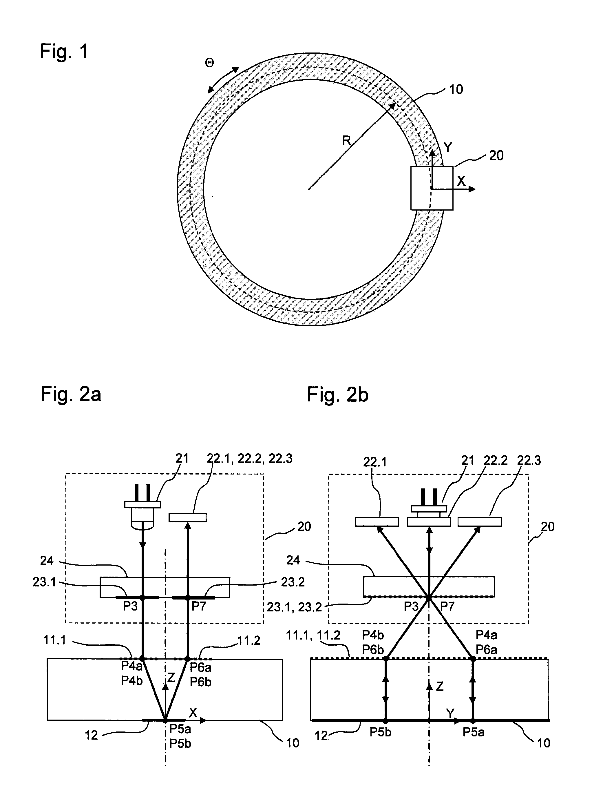
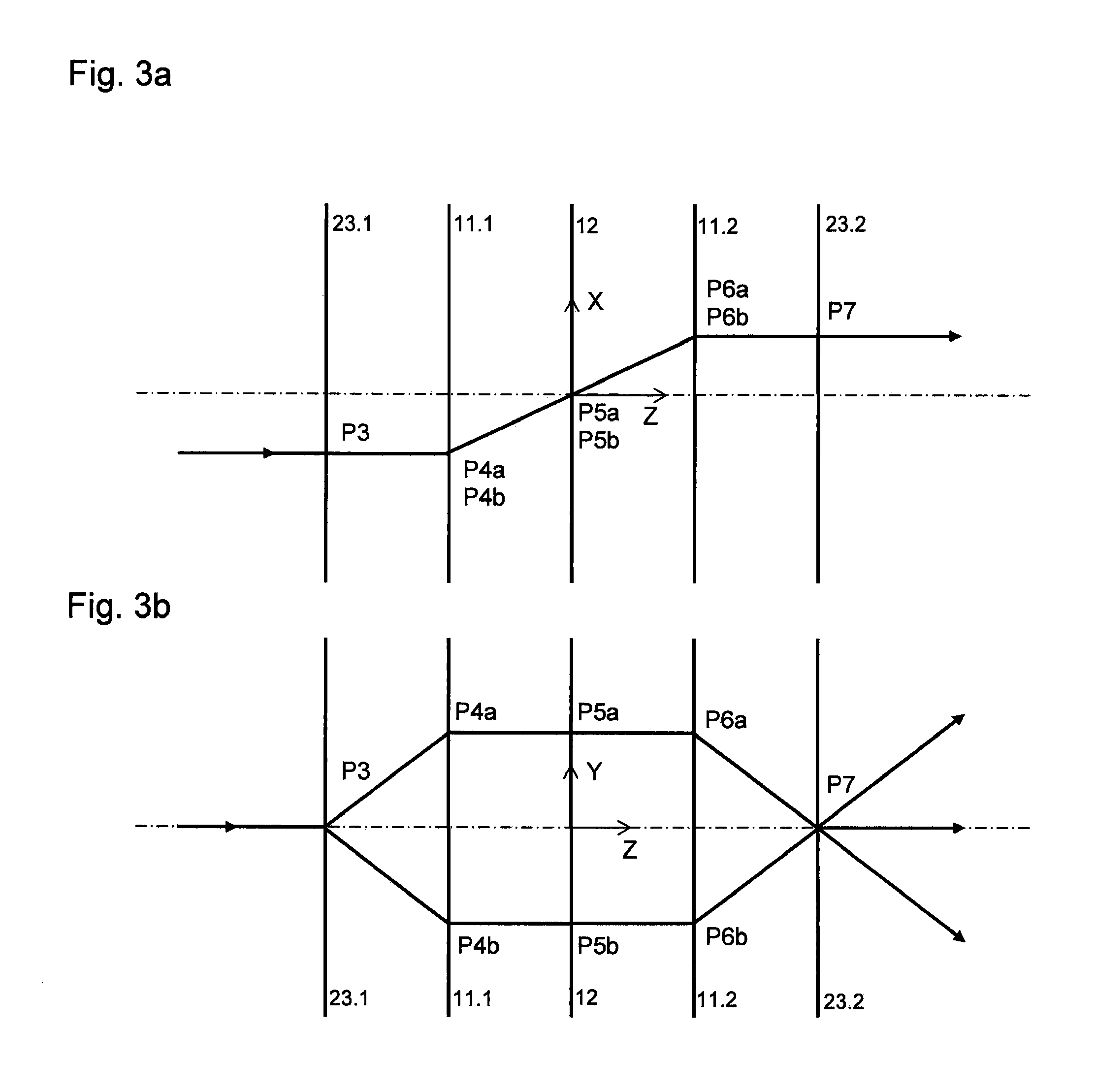
[0045]Before various exemplary embodiments and application examples of the optical angle-measuring device are explained below in detail, certain basic considerations will first be clarified, with reference to FIG. 1. Furthermore, individual geometrical quantities are illustrated in FIG. 1, which will be discussed during the further course of the description.

[0046]The optical angle-measuring device according to an example embodiment of the present invention is based on an interferential scanning principle and includes a scanning unit 20, as well as a graduated disk 10, rotating relative to it in the XY-plane, having at least one measuring graduation disposed on it. The measuring graduation is not shown in FIG. 1. To determine the rotational angle Θ of graduated disk 10 relative to scanning unit 20, a radial grating is provided as measuring graduation on graduated disk 10. The radial grating distorts the wave fronts of the diffracted beams of rays in the scanning beam path. Therefore,...


PUM


Abstract

In an optical angle-measuring device for ascertaining the relative movement between at least one scanning grating and a graduated disk having at least one measuring graduation, the scanning grating is in the form of a linear scanning grating, and the graduated disk includes a first and a second combined radial-circular grating as measuring graduation, and has a mirror. An incident beam of rays is initially split at the scanning grating into two partial beams of rays that then propagate in the direction of the first combined radial-circular grating and are diffracted there, then propagate in the direction of the mirror and are reflected there in the direction of the second combined radial-circular grating, subsequently propagate in the direction of the second combined radial-circular grating and are diffracted there, and then propagate in the direction of the scanning grating, where a superposition of the partial beams of rays results.

Description

CROSS-REFERENCE TO RELATED APPLICATIONS[0001]The present application claims priority to Application No. 10 2010 043 263.6, filed in the Federal Republic of Germany on Nov. 3, 2010, claims priority to Application No. 10 2011 081 879.0, filed in the Federal Republic of Germany on Aug. 31, 2011, and claims the benefit of U.S. Provisional Patent Application Ser. No. 61 / 409,646, filed on Nov. 3, 2010, each of which is expressly incorporated herein in its entirety by reference thereto.FIELD OF THE INVENTION[0002]The present invention relates to an optical angle-measuring device.BACKGROUND INFORMATION[0003]For the most part, high-resolution optical angle-measuring devices based on interferential scanning principles have only small mounting tolerances for the graduated disk having the measuring graduation disposed on it. A measuring device which addresses this problem is described in German Patent Application No. 10 2010 029 211.7. Wave-front distortions which result from the scanning of ra...

Claims


Application Information

Patent Timeline
Patent Type & Authority Applications(United States)
IPC IPC(8): G01B11/26
CPCG01D5/3473G01D5/38
Inventor HOLZAPFEL, WOLFGANG
Owner DR JOHANNES HEIDENHAIN GMBH
Why Eureka
Try Eureka