Self-Interference Suppression in Full-Duplex MIMO Relays

a relay and full-duplex technology, applied in the field of relays, can solve the problems of limiting the performance of relays, spectral efficiency penalties,

Active Publication Date: 2012-05-03
TELEFON AB LM ERICSSON (PUBL)
View PDF2 Cites 28 Cited by
  • Summary
  • Abstract
  • Description
  • Claims
  • Application Information

AI Technical Summary

Problems solved by technology

A drawback with half-duplex relays is that they require two orthogonal channels for transmission and reception, and thus incur a spectral efficiency penalty.
However, a critical drawback with the full-duplex operation is the resulting self-interference, caused by coupling from the relay's transmission to its own reception, which may severely limit the performance of the relay.

Method used


Image

  • Self-Interference Suppression in Full-Duplex MIMO Relays
  • Self-Interference Suppression in Full-Duplex MIMO Relays
  • Self-Interference Suppression in Full-Duplex MIMO Relays

Examples


Embodiment Construction

[0029]Embodiments of the present invention will be described more fully hereinafter with reference to the accompanying drawings, in which embodiments of the invention are shown. This invention may, however, be embodied in many different forms and should not be construed as limited to the embodiments set forth herein. Rather, these embodiments are provided so that this disclosure will be thorough and complete, and will fully convey the scope of the invention to those skilled in the art.

[0030]Henceforth in the description vectors are denoted with lower case letters in bold and italic and matrices are denoted with capital letters in bold and italic.

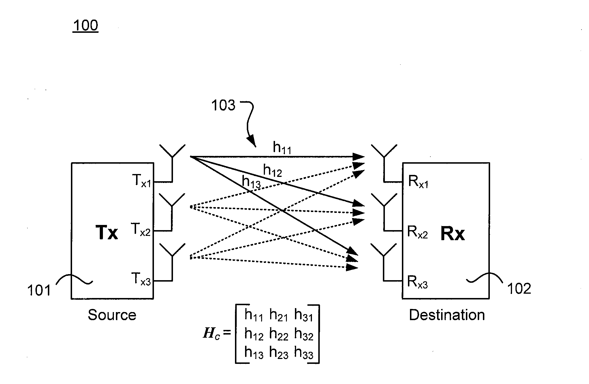
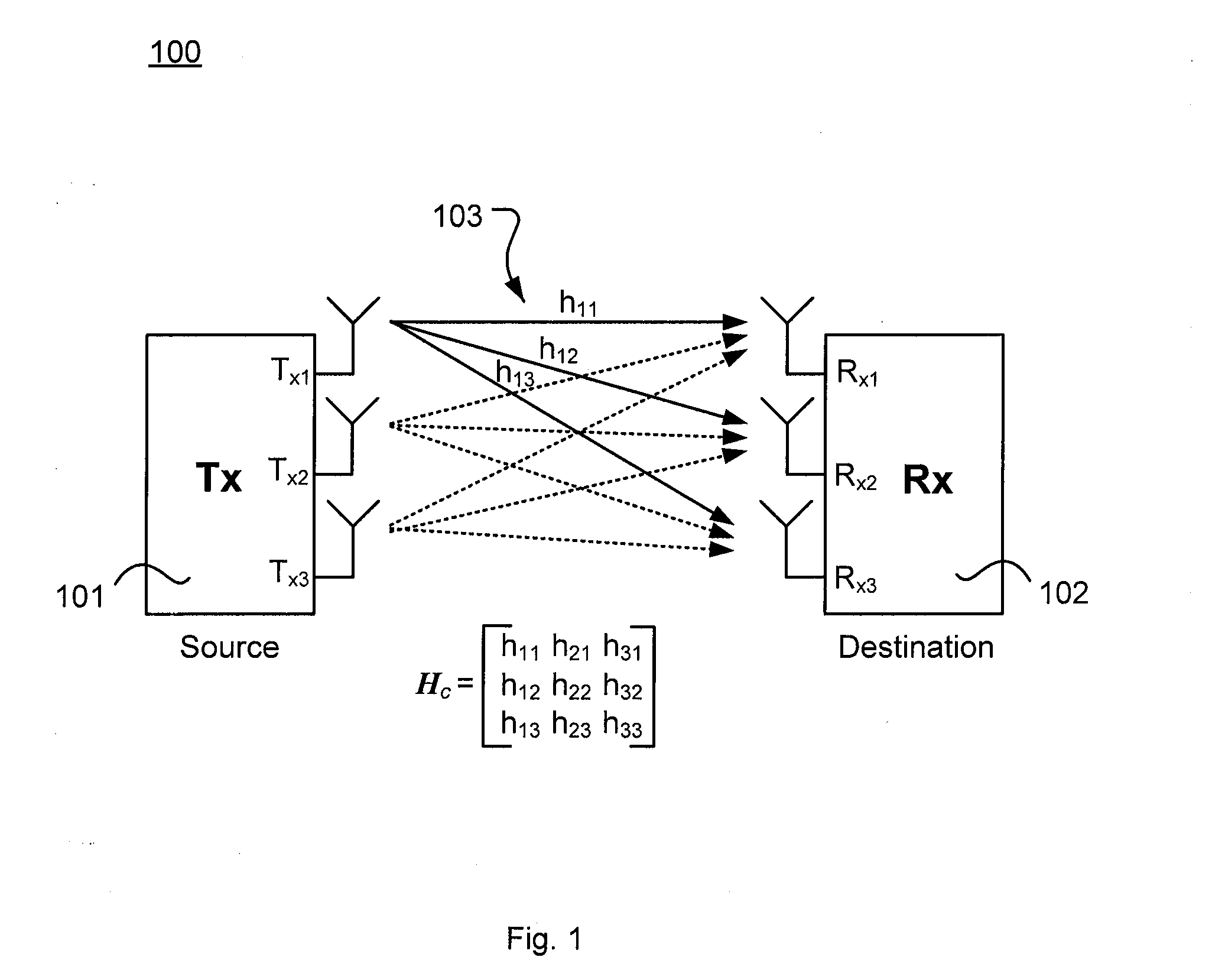
[0031]FIG. 1 shows an example of a multiple-input multiple-output (MIMO) wireless communication system 100 comprising a source 101, typically a transmitter (Tx), having three output antennas Tx1-Tx3, a destination 102, typically a receiver (Rx), having three input antennas Rx1-Rx3, and a communication channel 103. In this example there is on...


PUM


Abstract

A method, and an apparatus, for self-interference suppression in a relay (300) for wireless communication, wherein the relay (300) is arranged for receiving a signal r(n) transmitted from a transmitter (301), and for transmitting a self-interference suppressed transmit signal xr(n) to a receiver (305). The self-interference suppressed transmit signal xr(n) is achieved by determining (402) a receive suppression filter matrix Wr (302), determining a relay amplification matrix G (303), and determining (403) a transmit suppression filter matrix Wt (304), and then applying the suppression filters and the amplification matrix to the received signal r(n).

Description

TECHNICAL FIELD[0001]The invention relates in general to the field of relaying nodes, and more particularly, to the field of relays in wireless multiple-input multiple-output (MIMO) communication systems.BACKGROUND[0002]The use of MIMO architectures wireless communications systems promises to enhance the capacity of these wireless communications systems by taking advantage of the multipath propagation. The use of multiple transmit and receive antennas in a multipath environment, offers not only spectral efficiency through spatial multiplexing, but also increases reliability through diversity.[0003]Combining MIMO transceivers with relaying networks has been identified as a promising technique for extending the coverage area, combating the shadowing effects, decreasing the power requirements at the transmitter, and for reducing infrastructure deployment costs of the wireless communications systems. Relaying nodes may be employed to forward the data to the destination which is otherwis...

Claims


Application Information

Patent Timeline
Patent Type & Authority Applications(United States)
IPC IPC(8): H04B7/14
CPCH04B7/15528H04B7/15564
Inventor LIOLIOU, PANAGIOTAVIBERG, MATSCOLDREY, MIKAEL
Owner TELEFON AB LM ERICSSON (PUBL)
Why Eureka
Try Eureka