Device And Method For Use During Ligament Reconstruction

a ligament and device technology, applied in the field of ligament reconstruction surgery, can solve the problems of time-consuming and inaccurate manual calculations

Inactive Publication Date: 2012-05-03
SMITH & NEPHEW INC
View PDF6 Cites 36 Cited by
  • Summary
  • Abstract
  • Description
  • Claims
  • Application Information

AI Technical Summary

Problems solved by technology

These manual calculations are oft

Method used


Image

  • Device And Method For Use During Ligament Reconstruction
  • Device And Method For Use During Ligament Reconstruction
  • Device And Method For Use During Ligament Reconstruction

Examples


Embodiment Construction

[0018]The following description of the preferred embodiment(s) is merely exemplary in nature and is in no way intended to limit the disclosure, its application, or uses.

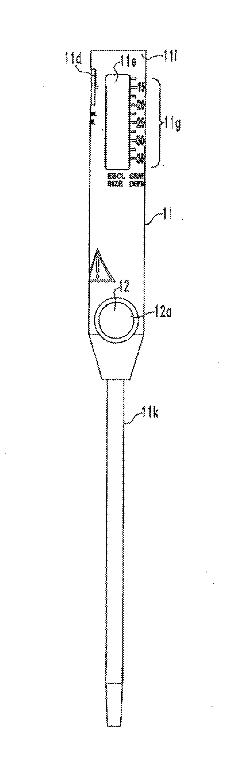
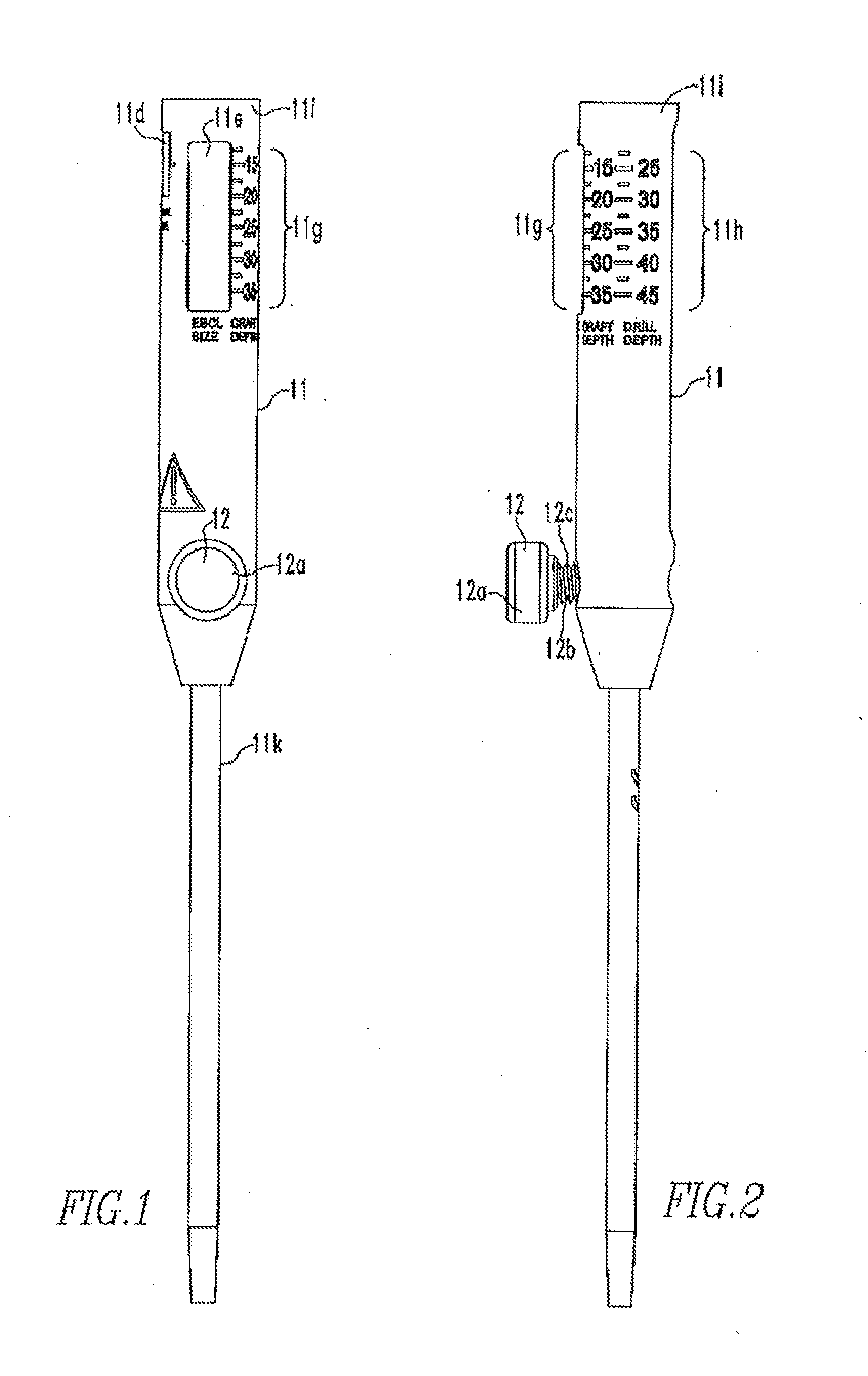
[0019]FIGS. 1-9 show the device 10 of the present disclosure and / or its components. The device 10 includes a handle 11 and a shaft 11k coupled to the handle 11. The handle 11 includes a first channel 11a having an opening 11a′, a second channel 11b having two openings 11b′, and a third channel 11c. The second channel 11b is perpendicular to the first and third channels 11a,11c. The handle 11 also includes a first window 11d, a second window 11e, and a groove 11f. A first set of numbers 11g and a second set of numbers 11h are located on the outer surface 11i of the handle 11. The second channel 11b has threads 11j located on an inner surface 11b″ of the second channel 11b. A knob assembly 12 having a knob 12a and a shaft 12b coupled to the knob 12a is coupled to the handle 11 such that the shaft 12b is disposed within...


PUM


Abstract

The present disclosure relates to a device for use during ligament reconstruction surgery. The device includes a handle and a shaft coupled to the handle, the handle including a first channel for housing of an insert, a second channel, a third channel for housing of the shaft, a first window, a second window, and a groove. A method for use during ligament reconstruction surgery is also disclosed.

Description

CROSS REFERENCE TO RELATED APPLICATIONS[0001]This application claims priority to U.S. patent application Ser. No. 61 / 315228, the disclosure of which is incorporated herein in its entirety.BACKGROUND[0002]1. Field of Technology[0003]The present disclosure relates to ligament reconstruction surgery, and more specifically, a device and method for determining lengths during reconstruction surgery.[0004]2. Related Art[0005]The creation of reconstruction tunnels in the femur for ligament reconstruction surgery is required for the attachment of a soft tissue graft, such as a semitendinosis tendon. The length of the femoral tunnel needs to be determined and calculations need to be made to, among other things, determine the appropriate lengths for the implants that are used to fixate the grafts in the tunnels. Currently, manual calculations are used. These manual calculations are often inaccurate and time consuming. Therefore, a device and method for more accurately making these calculations...

Claims


Application Information

Patent Timeline
IPC IPC(8): A61B17/16
CPCA61B17/1675A61B17/1714A61F2/0805A61F2002/0882A61F2250/0097A61B2090/062A61B5/1076A61B2090/0811A61B17/1764A61B17/8869A61B90/06A61B17/8897
Inventor ELLIS, DANIEL B.FERRAGAMO, MICHAEL CHARLESBEDERKA, BRYCEPERRIELLO, MICHAEL JAMES
Owner SMITH & NEPHEW INC
Why Eureka
Try Eureka