Apparatus and method for detection of solenoid current

a solenoid current and apparatus technology, applied in the direction of short-circuit testing, resistance/reactance/impedence, instruments, etc., can solve the problems of not being detected, unable to distinguish an open coil from a leaky fet in certain current ranges, and the feedback voltage is clos

Active Publication Date: 2012-05-10
KELSEY HAYES CO
View PDF9 Cites 13 Cited by
  • Summary
  • Abstract
  • Description
  • Claims
  • Application Information

AI Technical Summary

Benefits of technology

[0008]This invention relates to an apparatus and method for detection of small solenoid currents.

Problems solved by technology

Although this allows an open coil to be detected, it may be difficult to distinguish an open coil from a leaky FET in certain ranges of current.
If the leakage current is very low, there is little voltage drop across the coil and the resulting feedback voltage is close to the supply voltage and thus may not be detected.
If the leakage current is higher, but still relatively low, the feedback voltage is close to the open coil voltage and becomes difficult to distinguish from an open coil.
An unintended leakage current through a solenoid coil could result in a partial or complete opening or a closure of a valve, which could result in an undesired flow or an undesired blockage of brake fluid.

Method used


Image

  • Apparatus and method for detection of solenoid current
  • Apparatus and method for detection of solenoid current
  • Apparatus and method for detection of solenoid current

Examples


Embodiment Construction

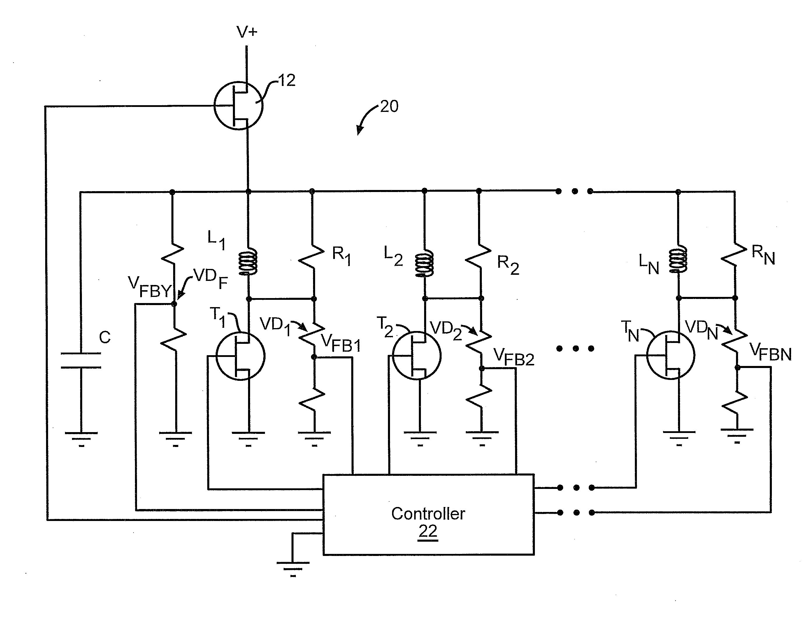
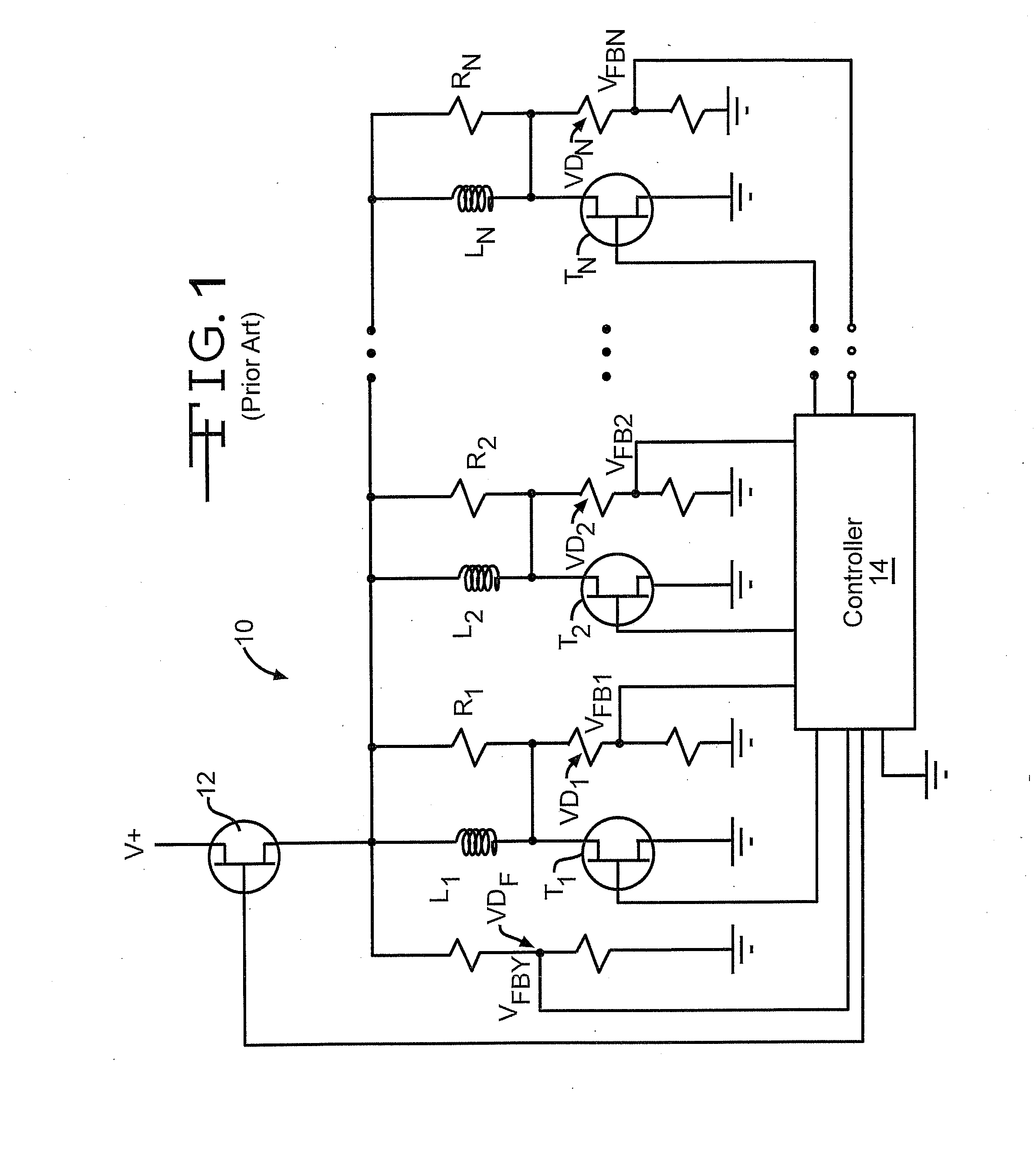
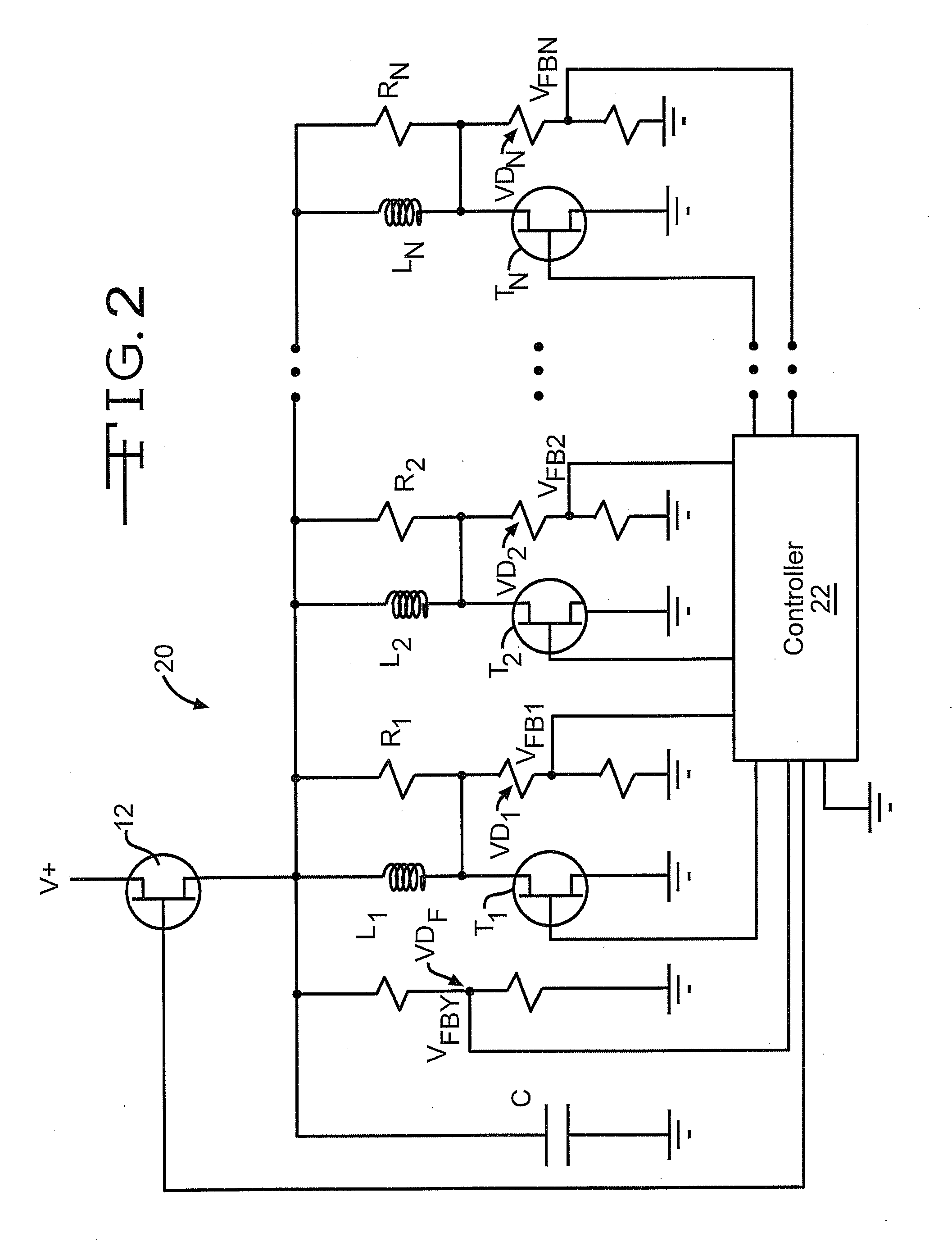
[0016]The present invention is directed toward a low cost circuit that allows detection of low levels of leakage current, not detectable through existing means. Referring now to the drawings, there is illustrated in FIG. 2 a control circuit 20 for controlling a plurality of solenoids that includes a capability for detecting solenoid currents that is in accordance with the present invention. Components appearing in FIG. 2 that are similar to components shown in FIG. 1 have the same numerical identifiers. The present invention provides a means to detect leakage currents in the range of 150 to 300 mA but can be adapted to detect leakage currents in other ranges. The circuit 20 is able to distinguish from a properly operating circuit without adding a more expensive current feedback to the controller.

[0017]The control circuit 20 includes a large capacitor C, which, in the preferred embodiment, has a value within the range of approximately 1 to 4.7 uF. However, the invention also may be p...


PUM


Abstract

An apparatus for detecting leakage current through a solenoid coil that includes a capacitor connected to one end of the solenoid coil and a feedback circuit that monitors the rate of decay of the capacitor voltage to determine if an excessive leakage current is present.

Description

BACKGROUND OF THE INVENTION[0001]This invention relates in general to systems that include solenoids and in particular to an apparatus and method for detection of small undesired solenoid currents.[0002]A typical prior art control circuit 10 used for multiple solenoids is shown in FIG. 1. The circuit 10 has a common high side Field Effect Transistor (FET) 12 with a drain terminal connected to a power supply V+. The source terminal of the high side FET 12 is connected to a high end of each of a plurality of solenoid coils labeled L1 through LN. The low end of each of the solenoid coils is connected to the drain of an associated low side FET, which is correspondingly labeled T1 through TN. The source of each of the low side FET's is connected to ground. The control circuit 10 also includes a plurality of resistors that are labeled R1 through RN, whose resistance is significantly higher than that of the solenoid coils. Each of the resistors R1 through RN is connected in parallel with a...

Claims


Application Information

Patent Timeline
Patent Type & Authority Applications(United States)
IPC IPC(8): G01R27/26G01R31/72
CPCG01R31/06G01R31/025G01R31/72G01R31/52
Inventor SCHLIEBE, PAUL
Owner KELSEY HAYES CO
Why Eureka
Try Eureka