Discharging control device for electric power conversion system

a technology of electric power conversion and control device, which is applied in the direction of field or armature current control, dynamo-electric motor/converter starter, dc source parallel operation, etc. it can solve the problems of not always correctly executed special discharging control operation, inability to ensure the correct drive of inverter and capacitor, etc., to avoid the deletion of diagnostic results

Active Publication Date: 2011-09-15
DENSO CORP
View PDF9 Cites 53 Cited by
  • Summary
  • Abstract
  • Description
  • Claims
  • Application Information

AI Technical Summary

Benefits of technology

[0025]In the case in which the diagnostic means executes the diagnostic operation when the starting switch is turned off, there is a possibility of deleting the diagnostic result when the discharging control device is...

Problems solved by technology

Accordingly, to correctly drive the inverter comprised of the power switching elements and the capacitor during the usual control operation does not guarantee to correctly drive the inverter and the capacitor during the special discharging control operation of discharging the electri...

Method used


Image

  • Discharging control device for electric power conversion system
  • Discharging control device for electric power conversion system
  • Discharging control device for electric power conversion system

Examples


first embodiment

[0057]A description will be given of a discharging control device according to a first embodiment of the present invention with reference to FIG. 1 to FIG. 8.

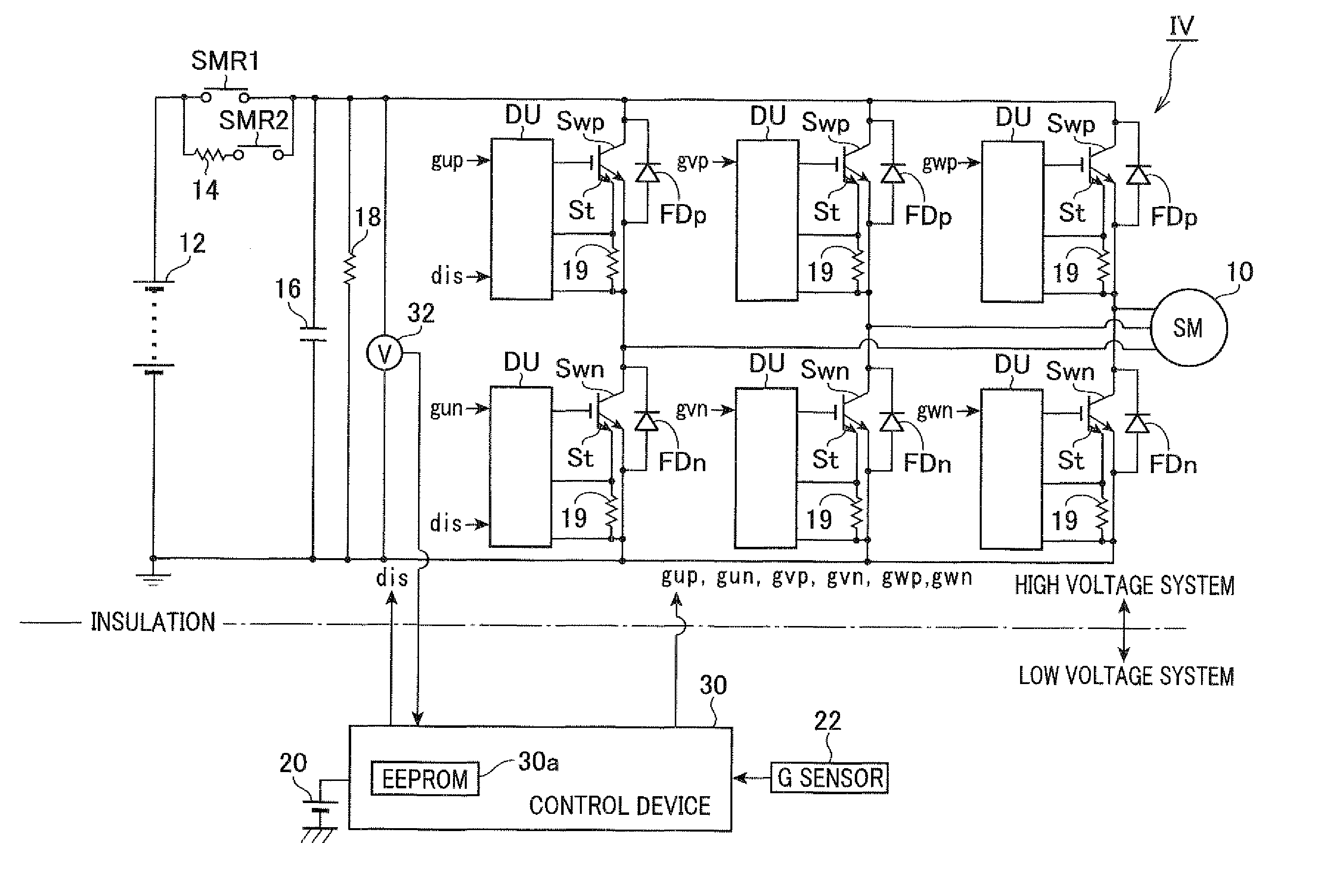
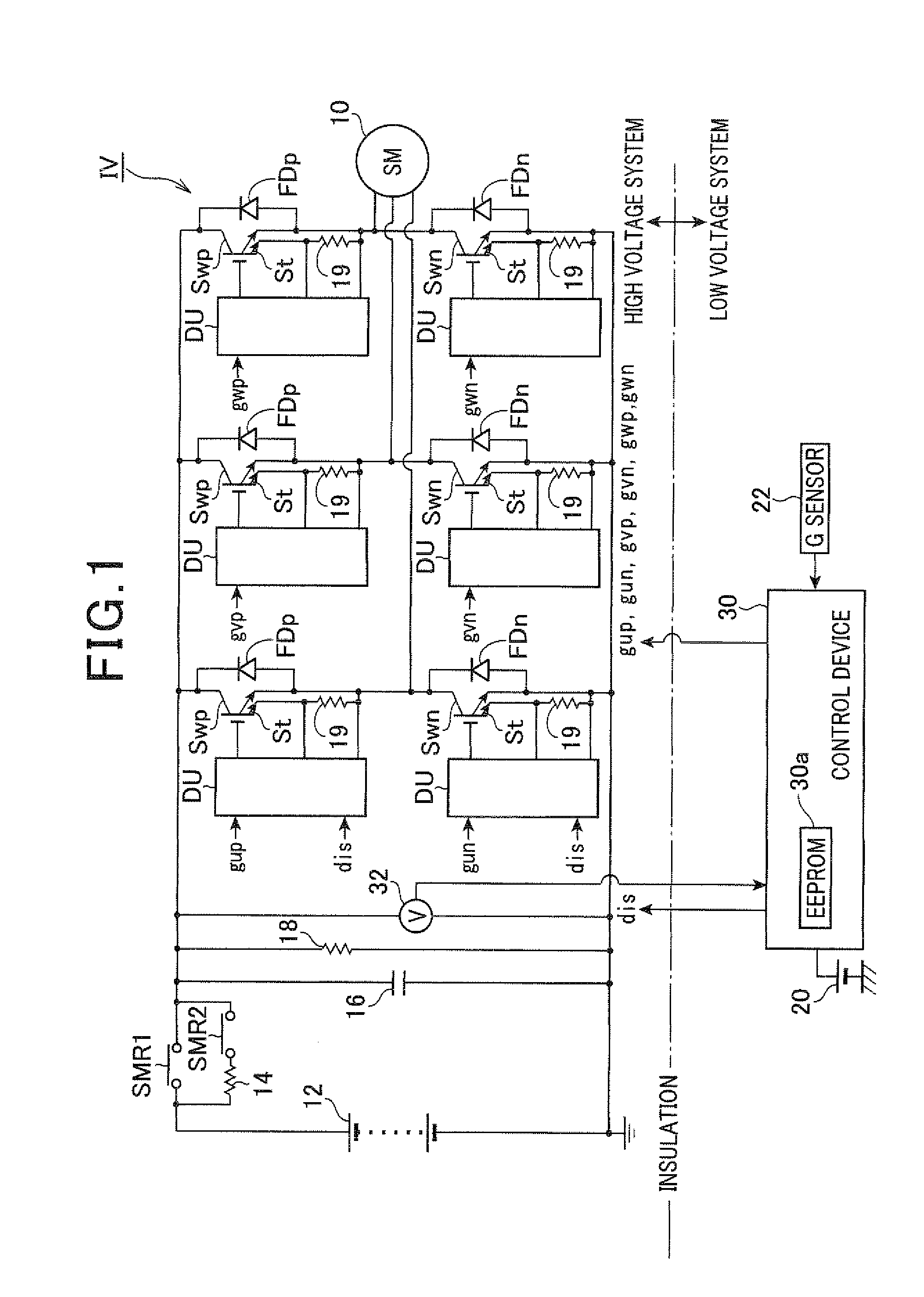
[0058]FIG. 1 is a view showing a system configuration of an electric power conversion system equipped with the discharging control device according to the first embodiment of the present invention. As shown in FIG. 1, a motor generator (or a synchronous motor) 10 is an on-vehicle main device. The motor generator is mounted to a hybrid motor vehicle (hereinafter, referred to the “motor vehicle”) and is mechanically connected to the driving wheels of the motor vehicle. The motor generator 10 is connected to a high voltage battery 12 such as a direct current (DC) power source through an inverter IV (a voltage conversion circuit) and a unit. The unit is comprised of a relay SMR2, a resistance 14 and a relay SMR1. In the unit, the relay SMR 2 and the resistance 14 are connected in series, and the relay SMR1 and the group of the rela...

second embodiment

[0127]A description will be given of the process of diagnosing whether or not the emergency discharging control can be correctly executed and completed under the control of the control device as the discharging control device according to the second embodiment of the present invention with reference to FIG. 9.

[0128]The difference in the diagnostic process between the second embodiment and the first embodiment will be explained below with reference to FIG. 9.

[0129]FIG. 9 is a flow chart showing the process of diagnosing whether or not the emergency discharging control can be correctly executed and completed according to the second embodiment of the present invention.

[0130]The same steps between the processes shown in FIG. 9 and FIG. 7 will be designated with the same step numbers.

[0131]As shown in FIG. 9, the control device 30 instructs the relay SMR1 to be turned off (namely, opened) in step S12. The operation flow goes to step S16. In step S16, the control device 30 instructs the c...

third embodiment

[0132]A description will be given of the process of discharging whether or not the emergency discharging control can be correctly executed and completed and completed under the control of the control device as the discharging control device according to the third embodiment of the present invention with reference to FIG. 10.

[0133]FIG. 10 is a flow chart showing the diagnosing process of detecting whether or not the emergency discharging control can be correctly executed and completed according to the third embodiment of the present invention.

[0134]The difference in the discharging control between the third embodiment and the first embodiment will be explained below with reference to FIG. 10. The same steps between the processes shown in FIG. 10 and FIG. 7 will be designated with the same step numbers.

[0135]In the process shown in FIG. 10, the control device 30 instructs the relay SMR1 to be turned off (namely, opened) in step S12. In step S18, the control device 30 generates and out...


PUM


Abstract

A discharge control device in an electric power conversion system mounted to a motor vehicle turns off a relay in order to instruct an electric power conversion circuit to supply a reactive current into a motor generator, and thereby to decrease a capacitor voltage to a diagnostic voltage. After this process, the discharge control device outputs an emergency discharging instruction signal dis in order to turn on both power switching elements at high voltage side and a low voltage side in the electric power conversion circuit. This makes a short circuit between the electrodes of the capacitor in order to discharge the capacitor, and executes a discharging control to detect whether or not an emergency discharging control is correctly executed and completed. The discharge control device detects whether or not the electric power stored in the capacitor is discharged on the basis of the voltage of a voltage sensor.

Description

CROSS-REFERENCE TO RELATED APPLICATION[0001]This application is related to and claims priority from Japanese Patent Application No. 2010-054415 filed on Mar. 11, 2010, the contents of which are hereby incorporated by reference.BACKGROUND OF THE INVENTION[0002]1. Field of the Invention[0003]The present invention relates to discharging control devices for electric power conversion systems comprised of a DC power source, an electric power conversion circuit, a capacitor, and an electrical switching means (or a switch open / close means), and the discharging control device having a discharging control means for adjusting a charged voltage of the capacitor to a voltage of not more than a predetermined voltage by controlling the electric power conversion circuit when the electrical switching means is turned off (namely, opened).[0004]2. Description of the Related Art[0005]Conventional techniques, for example, Japanese patent laid open publication No. JP 2009-232620 discloses a conventional ...

Claims


Application Information

Patent Timeline
IPC IPC(8): H02P3/08H02J7/04
CPCH02M2001/322H02M7/53871H02M1/322
Inventor MAEBARA, TSUNEOHAMANAKA, YOSHIYUKI
Owner DENSO CORP
Why Eureka
Try Eureka