Discharge Lamp Lighting Device, and Lighting Equipment and Lighting System Using the Device

a technology of lighting device and discharge lamp, which is applied in the direction of dc-ac conversion without reversal, process and machine control, instruments, etc., can solve the problems of large measurement error, difficulty in adequately measuring the life end of inability to use the technique for a determination on the life end of the smoothing capacitor in the inverter device, etc., to achieve the effect of simplifying the configuration

Inactive Publication Date: 2008-02-07
MATSUSHITA ELECTRIC WORKS LTD
View PDF4 Cites 51 Cited by
  • Summary
  • Abstract
  • Description
  • Claims
  • Application Information

AI Technical Summary

Benefits of technology

[0026] The lighting device, the illumination apparatus and the illumination system of the present invention can perform a determination on a life end of a smoothing capacitor accurately in a simplified configuration even when a discharge lamp is constantly turned on.

Problems solved by technology

Thus, these techniques cannot be used for a determination on a life end of a smoothing capacitor in an inverter device designed to be constantly driven.
This is undesirable from a practical standpoint.
Thus, it is difficulty to adequately measure the ripple component, resulting in a large measurement error.

Method used


Image

  • Discharge Lamp Lighting Device, and Lighting Equipment and Lighting System Using the Device
  • Discharge Lamp Lighting Device, and Lighting Equipment and Lighting System Using the Device
  • Discharge Lamp Lighting Device, and Lighting Equipment and Lighting System Using the Device

Examples


first embodiment

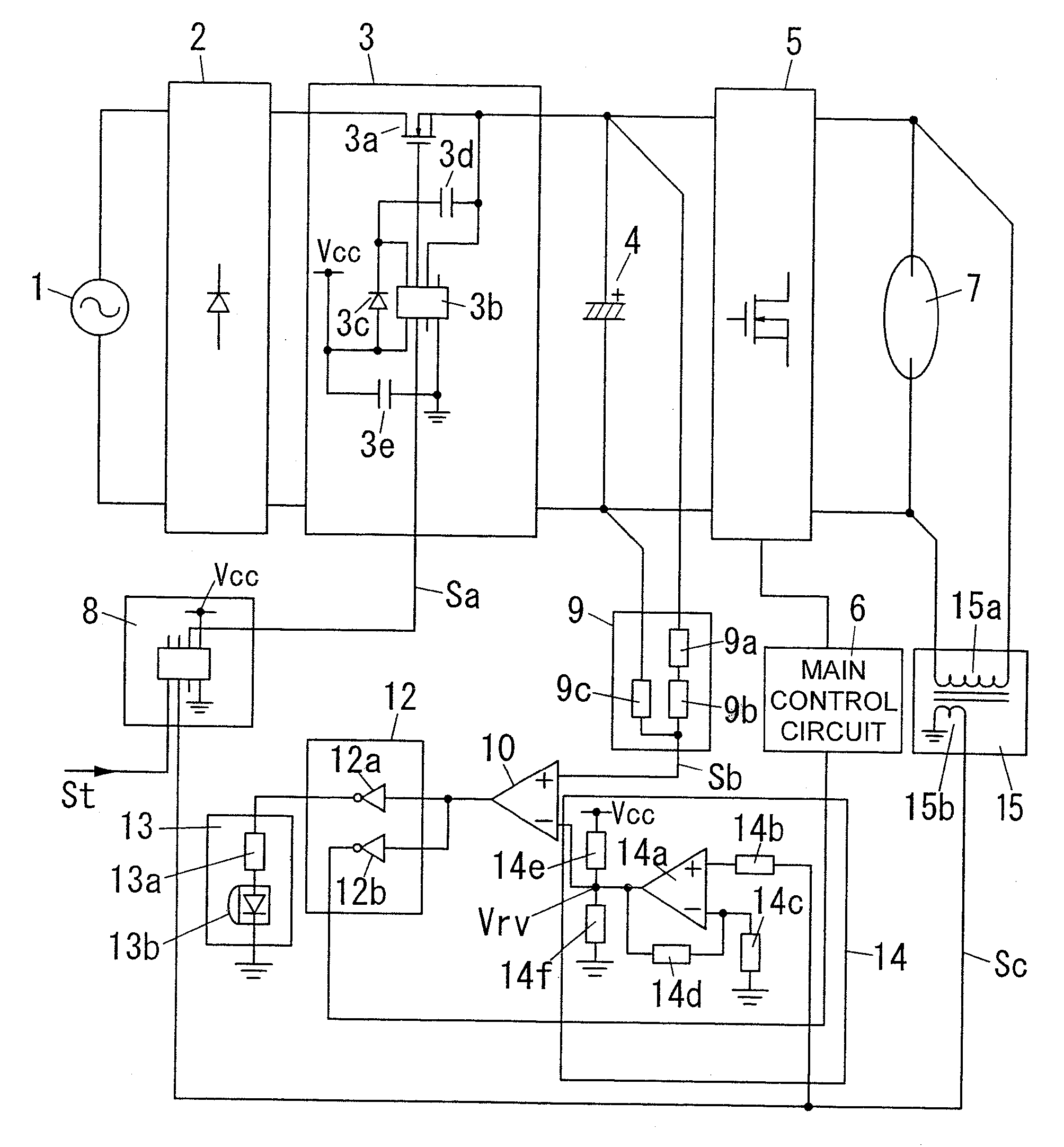
[0048]FIG. 1 shows a circuit configuration of a lighting device according to a first embodiment of the present invention. As shown in FIG. 1, this lighting device comprises a commercial power source 1, a rectifier2, a power supply / shutoff section 3, a smoothing capacitor 4, an inverter main circuit 5, a main control circuit 6, a discharge lamp 7, a timer circuit 8, a capacitor-voltage detection circuit 9, a comparator 10, a reference voltage source 11, an auxiliary control circuit 12, and an indicator circuit 13.

[0049] An AC power supplied from the commercial power source 1 is rectified to a DC power by the rectifier 2. The DC power is input to the smoothing capacitor 4 through the power supply / shutoff section 3, and smoothed by the smoothing capacitor 4. The smoothed DC power is converted to an AC power by the inverter main circuit 5, and the AC power is supplied to the discharge lamp 7. In this process, the main control circuit 6 is operable to control an operation of the inverte...

second embodiment

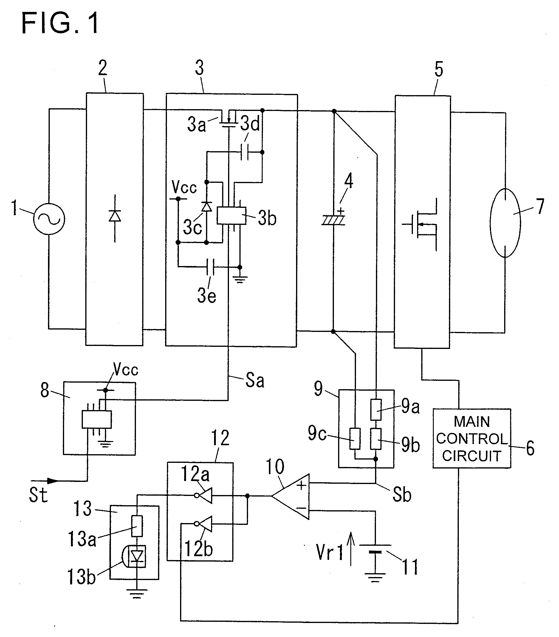
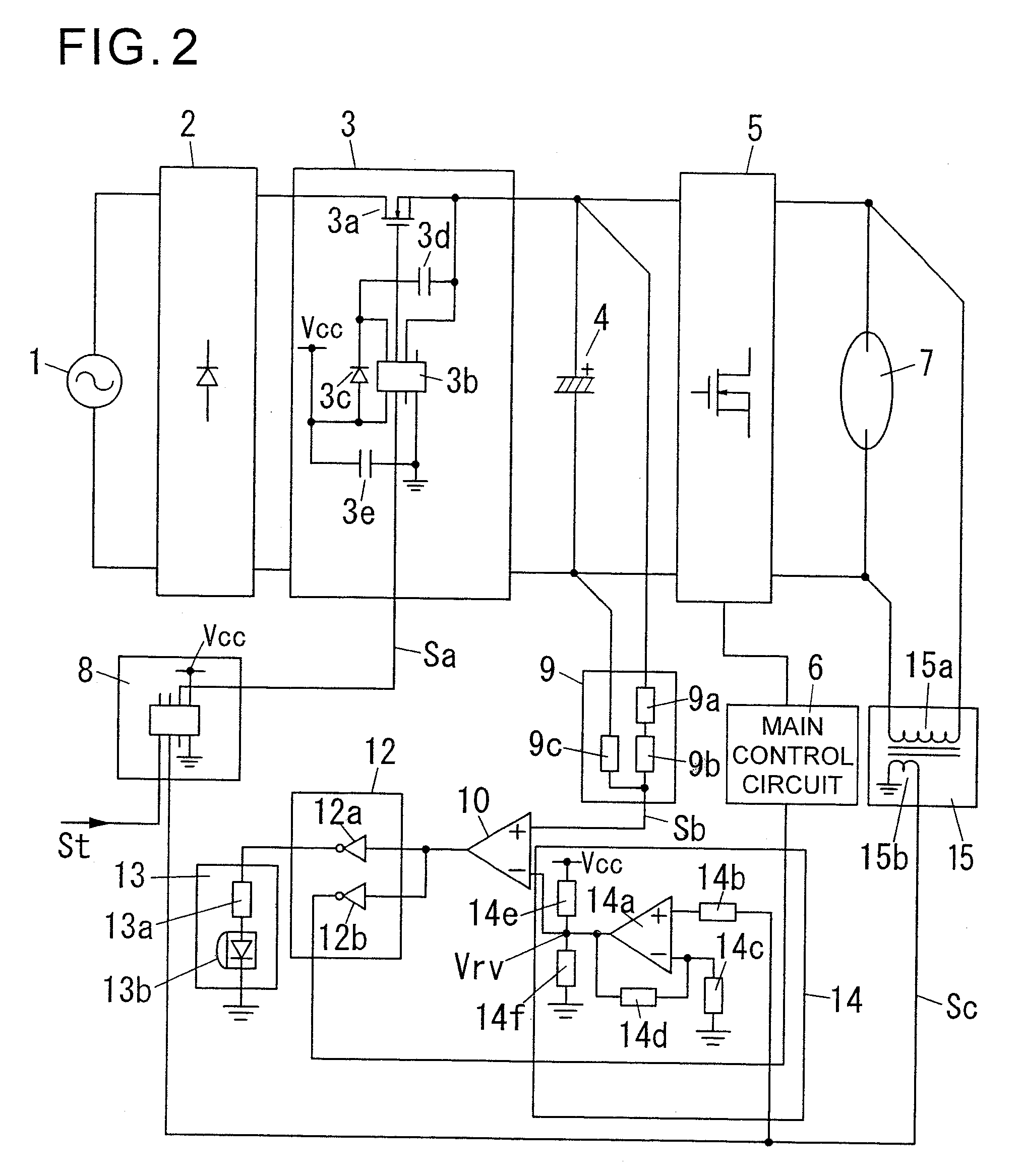
[0062] With reference to FIG. 2, a second embodiment of the present invention will be described below. FIG. 2 shows a circuit configuration of a lighting device according to the second embodiment. The lighting device according to the second embodiment is different from the lighting device according to the first embodiment only in the following points. A first difference is that a reference voltage generation circuit 14 is provided in place of the reference voltage source 11. A second difference is that a transformer having a primary winding 15a connected in parallel to a discharge lamp 7 and a secondary winding 15b magnetically coupled to the primary winding 15a is provided. The remaining configuration is the same as that of the lighting device according to the first embodiment. Thus, for avoiding duplication of description, the same element or component as that in the first embodiment is defined by the same reference numeral or code, and its description will be omitted.

[0063] The ...

third embodiment

[0070] With reference to FIG. 3, a third embodiment of the present invention will be described below. FIG. 3 shows a circuit configuration of a lighting device according to the third embodiment. The lighting device according to the third embodiment is different from the lighting device according to the second embodiment only in the following points. A first difference is that a comparator 16 for determining a life end of a discharge lamp 7, and resistors 17a, 17b for dividing a control power source Vcc to generate a reference voltage Vr4, are provided. A second difference is that an auxiliary control circuit 12 and an indicator circuit 13 are different in configuration from those in the second embodiment. The remaining configuration is the same as that of the lighting device according to the second embodiment. Thus, for avoiding duplication of description, the same element or component as that in the second embodiment is defined by the same reference numeral or code, and its descrip...


PUM


Abstract

A level shift IC (3b) of a power supply/shutoff section (3) is operable, when a shutoff signal (Sa) is input from a timer circuit (8) for a time T during an ON state of a discharge lamp (7), to turn off a MOSFET (3a) so as to shut off power supply to a smoothing capacitor (4). When a detection signal (Sb) of a capacitor voltage is lowered to a value less than a reference voltage Vr1 during input of the shutoff signal (Sa), an output of a comparator (10) is changed from an H level to an L level in an inverted manner. In conjunction with this change, respective outputs of an auxiliary control circuit (12) and a NOT element (12a, 12b) are changed from an L level to an H level in an inverted manner. As a result, a current flows from the NOT element (12a) to an LED (13b) through a resistor (13a) to turn on the LED (13b). Thus, a life end of the smoothing capacitor 4 is annunciated, and a main control circuit (6) is operable to suppress an output of an inverter main circuit (5).

Description

TECHNICAL FIELD [0001] The present invention relates to a discharge lamp lighting device for lighting a discharge lamp (hereinafter referred to shortly as “lighting device”), and an illumination apparatus and an illumination system using the lighting device. BACKGROUND ART [0002]FIG. 7 shows a circuit configuration of a conventional lighting device. As shown in FIG. 7, in this conventional lighting device, an AC power of a commercial power source 101 is rectified to a DC power by a rectifier 102. After this DC power is smoothed by a smoothing capacitor 103 and then converted to an AC power by an inverter main circuit 104, the AC power is supplied to a discharge lamp 106. A main control circuit 105 is operable to control an operation of the inverter main circuit 104 so that the AC power to be supplied to the discharge lamp 106 is controlled in a desired manner. [0003] The smoothing capacitor 103 requires having a large capacitance. Thus, an aluminum foil electrolytic capacitor is typ...

Claims


Application Information

Patent Timeline
Patent Type & Authority Applications(United States)
IPC IPC(8): H05B37/02G01R31/00H02M7/12H02M7/48H05B41/24
CPCG01R31/028G01R31/24H02M7/48Y02B20/208H05B41/2923H05B41/2926Y02B20/202H05B41/2886G01R31/64Y02B20/00
Inventor GORIKI, TAKESHINORO, KOJIFUKUMORI, NORIYUKIFUKUDA, KENICHI
Owner MATSUSHITA ELECTRIC WORKS LTD
Why Eureka
Try Eureka