Laser scanning sensor

a laser scanning and sensor technology, applied in the field of laser scanning sensors, can solve the problems that dirt on the cover of the laser light receiving portion or the like may have an adverse influence on measurement accuracy, and achieve the effect of reliably detecting a distant human

Active Publication Date: 2012-05-10
OPTEX CO LTD
View PDF1 Cites 17 Cited by
  • Summary
  • Abstract
  • Description
  • Claims
  • Application Information

AI Technical Summary

Benefits of technology

[0019]With the laser scanning sensor of the present invention, it is possible to reliably detect a distant human body, prevent an improper alert to the effect that the cover is dirty in the case where, for example, t

Problems solved by technology

On the other hand, in apparatuses that detect intruders by using a laser range finder or apparatuses that are mounted on a vehicle and measure the distance

Method used


Image

  • Laser scanning sensor
  • Laser scanning sensor
  • Laser scanning sensor

Examples


Embodiment Construction

[0026]Embodiments of the present invention will be described below with reference to the drawings.

[0027]Schematic Configuration

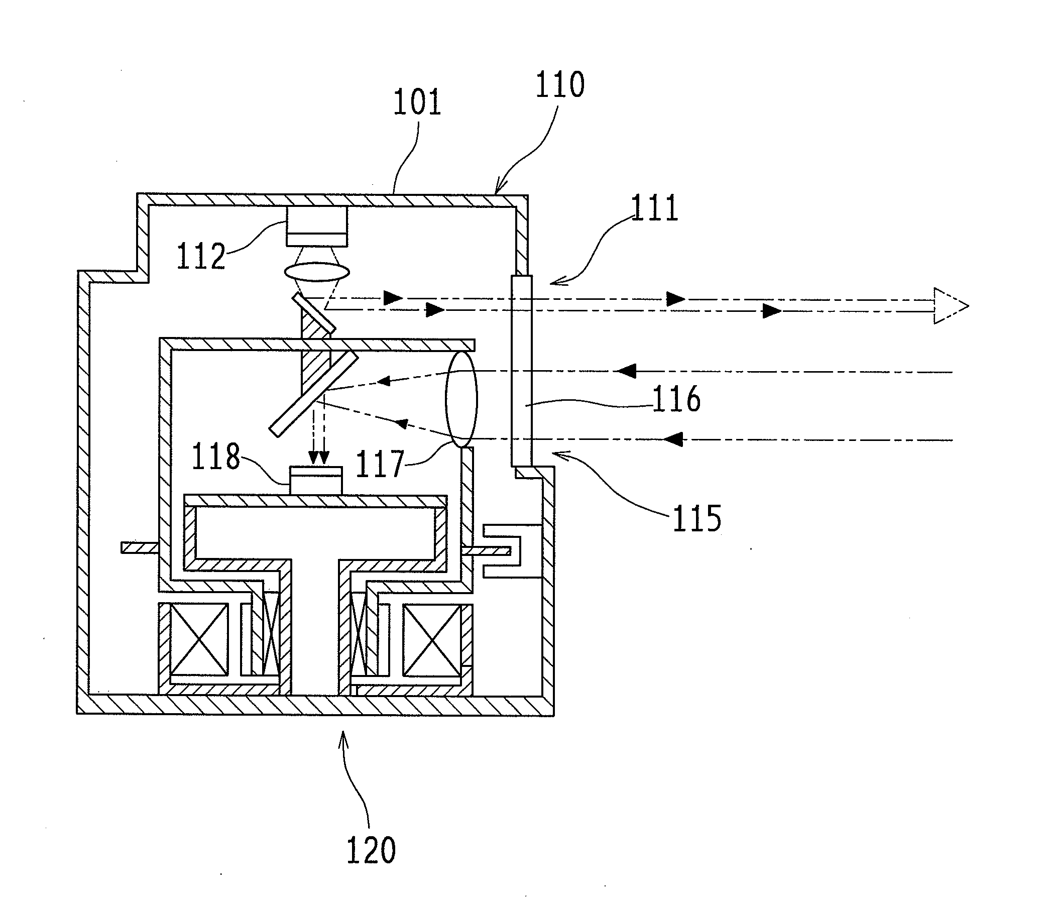
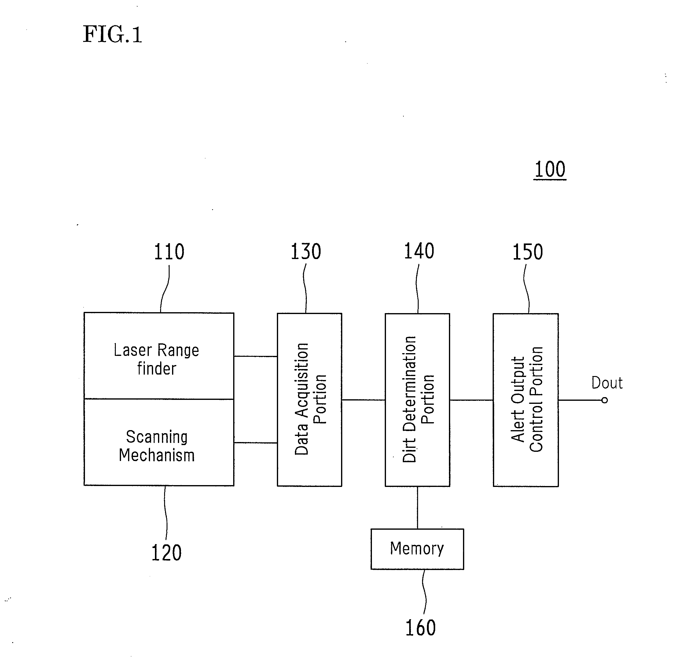
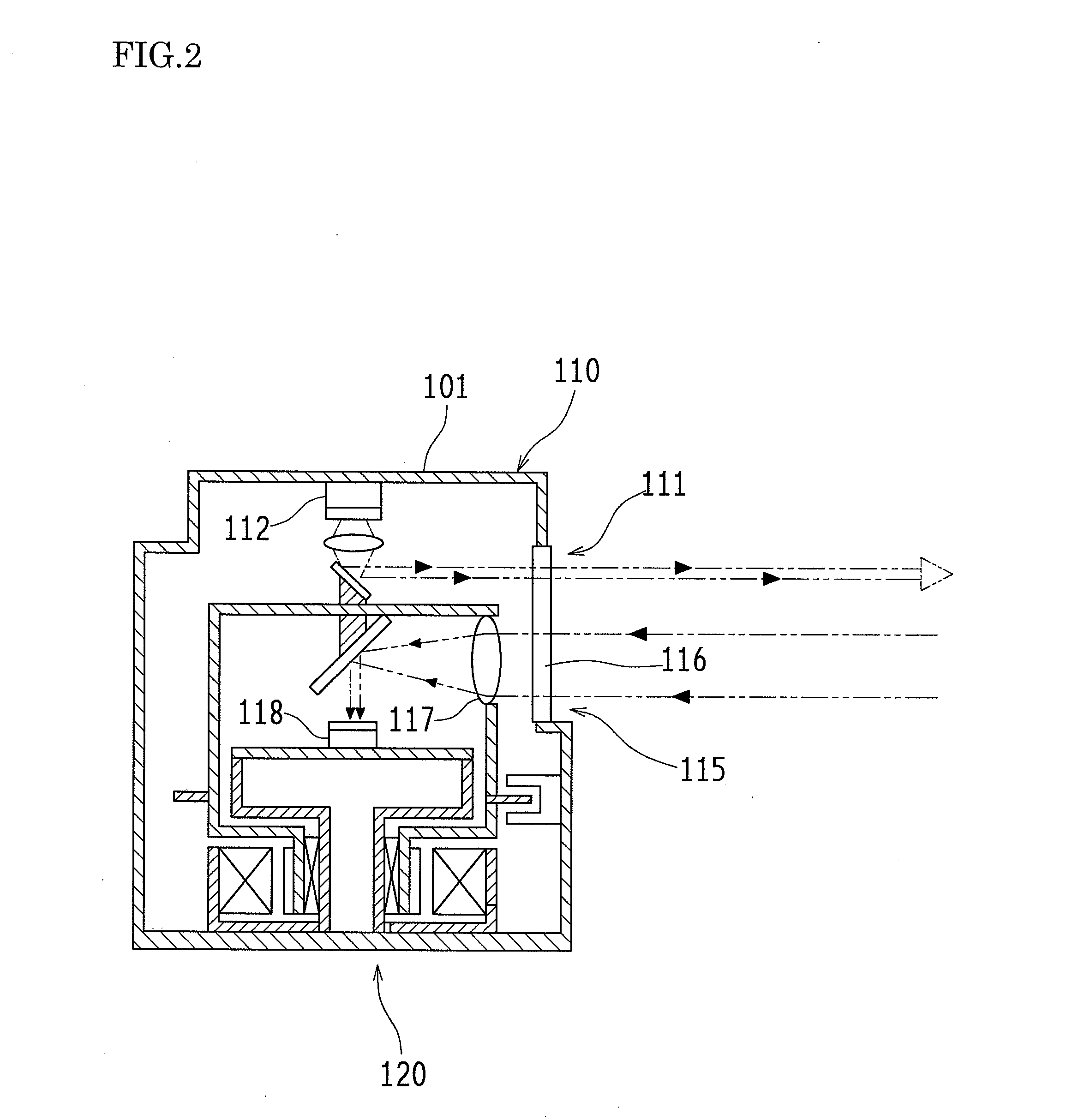
[0028]FIG. 1 is a block diagram illustrating a schematic electrical configuration of an entire laser scanning sensor 100 according to an embodiment of the present invention. FIG. 2 is a cross-sectional view illustrating a schematic configuration of mainly a laser range finder 110 and a scanning mechanism 120 of the laser scanning sensor 100. FIG. 3 is a schematic explanatory diagram of a basic detection area A100 formed by the laser scanning sensor 100.

[0029]As shown in FIG. 1, the laser scanning sensor 100 includes the laser range finder 110, the scanning mechanism 120, a data acquisition portion 130, a dirt determination portion 140, an alert output control portion 150, and a memory 160. As shown in FIG. 2, the laser range finder 110 includes a laser light emitting portion 111 including a laser light emitting element 112, and a laser light receiving portio...


PUM


Abstract

A laser scanning sensor (100) of an embodiment of the present invention includes a laser range finder (110), a scanning mechanism (120), a data acquisition portion (130), a dirt determination portion (140), an alert output control portion (150) and a memory (160). The laser range finder (110) is arranged inside a housing (101) having an opening portion, and the opening portion is covered with a lens cover (116) that can transmit laser light. In the dirt determination portion (140), a predetermined threshold to be compared with a received light level is changed based on maximum detection distance information in each measurement direction.

Description

TECHNICAL FIELD[0001]The present invention relates to, for example, laser scanning sensors that detect intruders into premises of a building or the like, and particularly, relates to laser scanning sensors capable of maintaining reliability of detection of intruders or the like as much as possible even when the cover of a light-receiving portion is dirty.BACKGROUND ART[0002]A “security system” has been proposed in which intruders are detected by using a laser range finder that uses laser light as its light source (e.g., see Patent Document 1). Also, an “object distinction method using an area sensor” has been proposed in which laser light is used to accurately distinguish pedestrians or the like, although it is slightly different from security devices or security systems (e.g., see Patent Document 2).[0003]Furthermore, in view of problems in these conventional techniques, the inventor of the present invention has already proposed a laser area sensor in which it is possible to easily...

Claims


Application Information

Patent Timeline
IPC IPC(8): G01C3/08G01S17/04
CPCG01S7/4813G01S17/026G01S2007/4975G08B13/183G01S7/497G01S17/42G01S17/04
Inventor IWASAWA, MASASHICHO, SEONGHO
Owner OPTEX CO LTD
Why Eureka
Try Eureka