This helps you quickly interpret patents by identifying the three key elements:
Problems solved by technology
Method used
Benefits of technology
Benefits of technology
[0018]According to the present invention, it becomes possible to suppress variances of characteristics of the metal reflective film due to a temporal change.
[0019]In addition, according to the present invention, the metal reflective film can be formed of an inexpensive material.
[0020]Therefore, according to the present invention, a durable read-only optical recording medium having less variances in characteristics of a metal reflective film due to a temporal change can be realized at low costs.
Problems solved by technology
However, since a silver alloy is somewhat expensive as a material of the read-only optical recording medium, a cost increases.
Method used
Image
Click on the blue label to locate the original text in one second.
Reading with bidirectional positioning of images and text.
Examples
first embodiment
1. FIRST EMBODIMENT
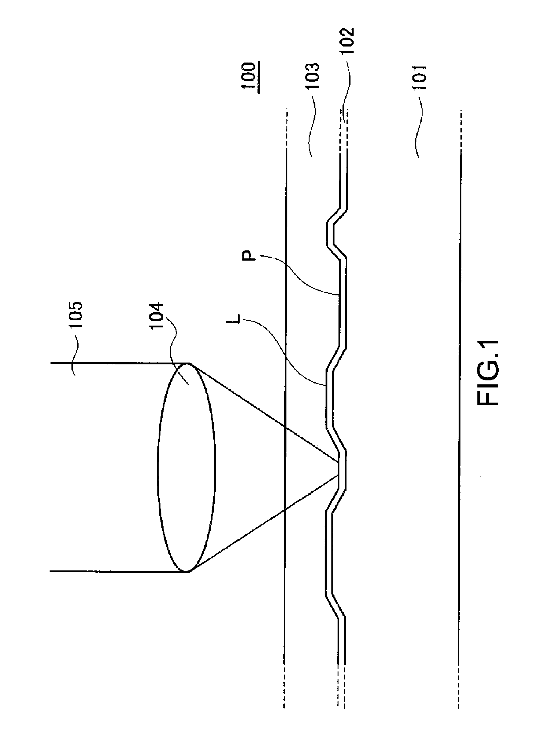
[0038]FIG. 1 shows a schematic structural diagram (cross-sectional diagram) of a read-only optical recording medium according to a first embodiment of the present invention.
[0039]An optical disc 100 has a multilayer structure in which a metal reflective film 102 and a cover layer 103 are laminated on a substrate 101.
[0040]As the substrate 101, a plastic substrate formed of, for example, polycarbonate can be used.
[0041]A surface of the substrate 101 that comes into contact with the metal reflective film 102 has a concavo-convex cross-sectional shape. The concave cross-sectional portions correspond to pits P, and the convex cross-sectional portions correspond to lands L. Specifically, the convex cross-sectional portions onto which laser light 105 is irradiated from the cover layer 103 and that protrude toward a light-incident side of the laser light 105 are the lands L. Information is recorded using a combination of the pits P and lands L, more specifically, lengths...
second embodiment
2. SECOND EMBODIMENT
[0061]A structure of a read-only optical recording medium according to a second embodiment of the present invention will be described.
[0062]A cross-sectional structure of the read-only optical recording medium is the same as that of the optical disc 100 of the first embodiment shown in FIG. 1.
[0063]In this embodiment, the metal reflective film 102 is formed of an Al alloy represented by Al100-x-zXxZz (x and z each represent atomic %) as in the first embodiment. In addition, X includes Ti, Z includes Fe, a content x of X (atomic %) is 1.0 to 3.0, and a content z of Z (atomic %) is 0.05 to 1.0.
[0064]In this embodiment, the metal reflective film 102 of the optical disc 100 shown in FIG. 1 has a structure as a recordable metal reflective film in which sub-data different from main data recorded by pits and lands is recorded.
[0065]When the content x of X including Ti exceeds 3.0 atomic %, it becomes difficult to make the metal reflective film 102 sufficiently uniform.
[...
experiment 1
Comparison of Temporal Changes of Reflectance
[0189]For estimating a lifetime of the read-only optical recording medium, temporal changes of reflectance of a metal reflective film were compared by an acceleration test.
PUM
Property
Measurement
Unit
Wavelength
aaaaa
aaaaa
Abstract
[Object] To provide a durable read-only optical recording medium having less variances in characteristics of a metal reflective film due to a temporal change.[Solving Means] Provided is a read-only optical recording medium (100) including: a substrate (101); an information recording surface onto which information is recorded by combining pits (P) and lands (L); and a metal reflective film (102) that is provided in contact with the information recording surface and represented by Al100-x-zXxZz, where x and z each represent an atomic %, X is constituted of an element including at least Ti, Z is constituted of an element including at least Fe, x is 1.0 to 3.0, and z is 0.05 to 1.0.
Description
TECHNICAL FIELD[0001]The present invention relates to a read-only optical recording medium including a metal reflective film.BACKGROUND ART[0002]For an optical disc, particularly a read-only ROM (Read Only Memory) disc, as an optical recording medium, a large amount of replica substrates can be produced at low costs in a short time by injection molding of plastic from a single stamper. Therefore, optical recording media are widely used as package media.[0003]Incidentally, for preventing a copyright infringement, a method of adding identification information that differs for each disc is being considered. As the method of adding identification information, there is proposed a method of, for example, recording sub-data onto a metal reflective film (e.g., see Patent Document 1).[0004]In an optical disc of Patent Document 1, an Ag (silver) alloy is used as the metal reflective film.[0005]The metal reflective film formed of an Ag alloy can be used not only in a read-only optical recordin...
Claims
Application Information
Patent Timeline
Application Date:The date an application was filed.
Publication Date:The date a patent or application was officially published.
First Publication Date:The earliest publication date of a patent with the same application number.
Issue Date:Publication date of the patent grant document.
PCT Entry Date:The Entry date of PCT National Phase.
Estimated Expiry Date:The statutory expiry date of a patent right according to the Patent Law, and it is the longest term of protection that the patent right can achieve without the termination of the patent right due to other reasons(Term extension factor has been taken into account ).
Invalid Date:Actual expiry date is based on effective date or publication date of legal transaction data of invalid patent.

