Attachment ring for attaching a shield of an electrical cable to a backshell

a technology of attaching a shield and an electrical cable, which is applied in the direction of coupling protective earth/shield arrangement, shape memory alloy connection, coupling device connection, etc., can solve the problem of increasing the cost of terminating the electrical cable to the electrical connector, reducing the number of electrical cables that can be terminated to the electrical connector within a given time period, and difficult to hold the attaching ring in position over the end of the shield

Active Publication Date: 2012-05-10
TYCO ELECTRONICS LOGISTICS AG (CH)
View PDF0 Cites 6 Cited by
  • Summary
  • Abstract
  • Description
  • Claims
  • Application Information

AI Technical Summary

Problems solved by technology

But, positioning the attachment ring over the end of the shield before the shield is received over the fitting may be time consuming and / or difficult, which may increase a cost of terminating the electrical cable to the electrical connector and / or may decrease the number of electrical cables that can be terminated to electrical connectors within a given time period.
For example, it may be difficult to hold the attachment ring in position over the end of the shield as the end of the shield is received over the fitting.
Once the end of the shield is received over the fitting of the backshell, it may be time consuming and / or frustrating for a person to locate the attachment ring along the length of the cable and position the attachment ring back over the end of the shield.
The attachment ring must then be moved along the entire length of the electrical cable to the end that is being terminated to the electrical connector, which may also be time consuming and / or difficult.
Another disadvantage of at least some known attachment rings is removal of the attachment rings from the shield.
However, due to the relatively strong shape memory materials that are used to fabricate at least some known attachment rings, cutting the attachment ring may be difficult, time consuming, and / or require special tooling (e.g., an electrical power tool and / or the like).
Moreover, cutting the attachment ring may damage the fitting of the backshell, the electrical cable, and / or the shield in the proximity of the cutting operation, which may result in a costly repair.

Method used


Image

  • Attachment ring for attaching a shield of an electrical cable to a backshell
  • Attachment ring for attaching a shield of an electrical cable to a backshell
  • Attachment ring for attaching a shield of an electrical cable to a backshell

Examples


Embodiment Construction

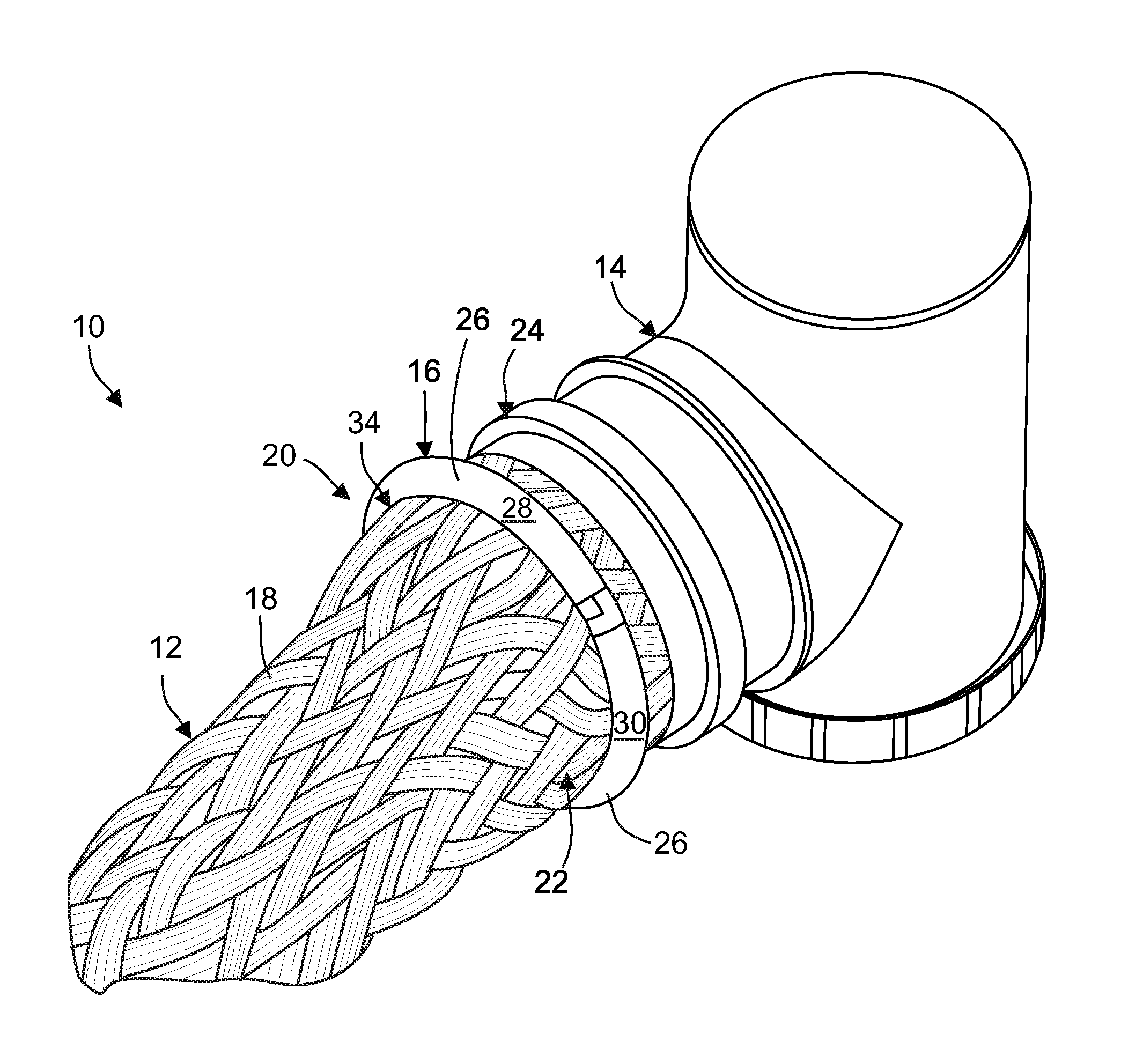
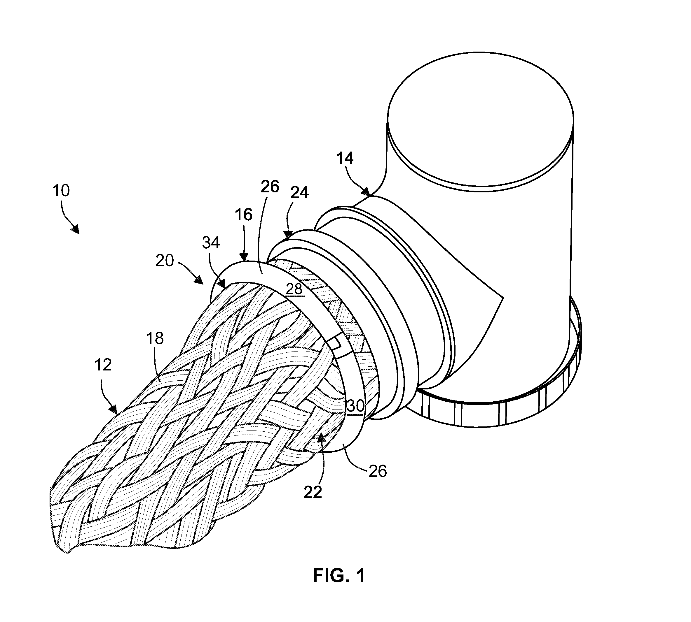
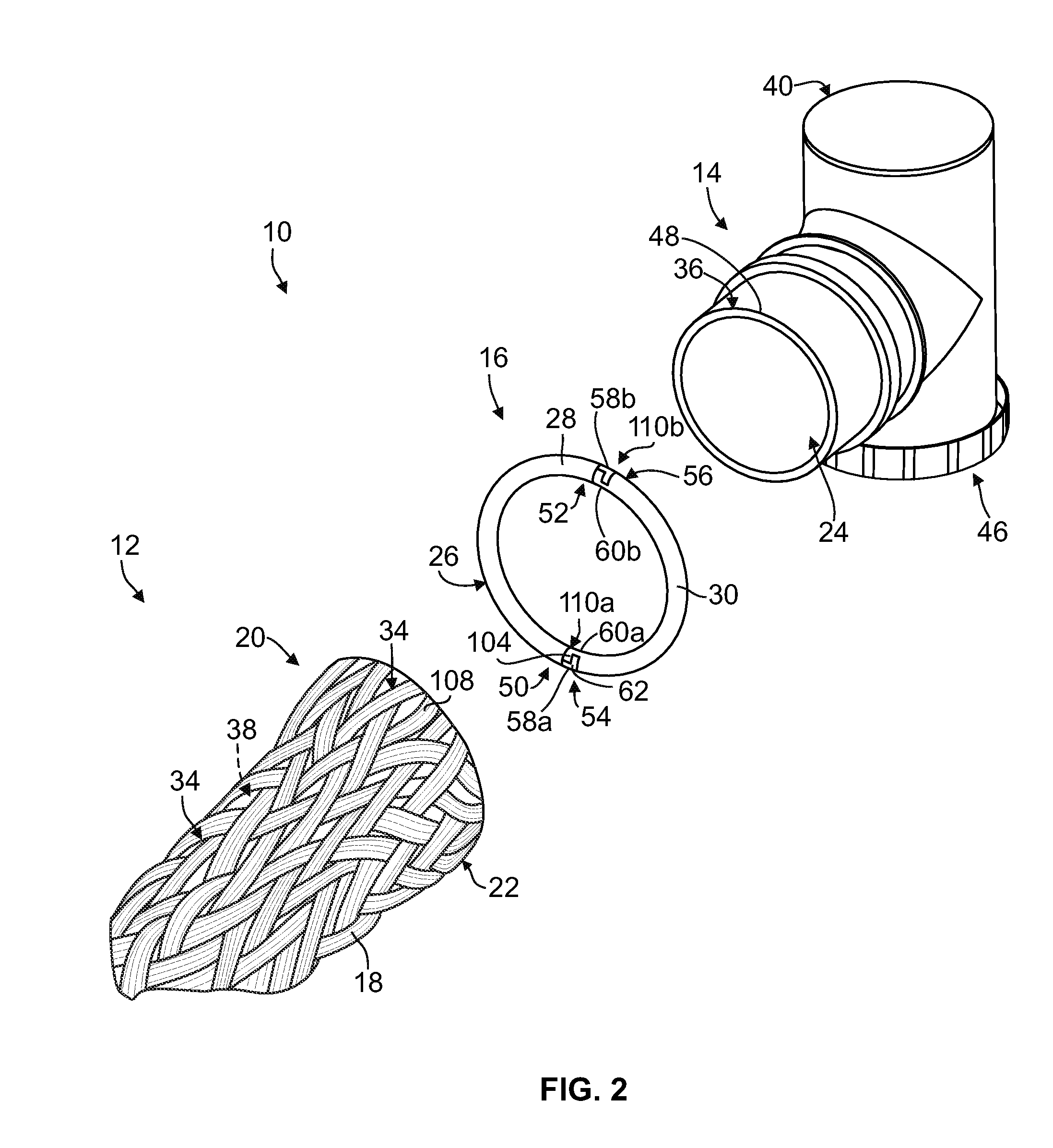
[0015]FIG. 1 is a perspective view of a portion of an exemplary embodiment of an electrical cable assembly 10. The electrical cable assembly 10 includes an electrical cable 12, a backshell 14, and an attachment ring 16. The electrical cable 12 includes a shield 18. The backshell 14 is configured to be connected to an electrical connector (not shown) that terminates an end 20 of the electrical cable 12. The termination of the electrical cable end 20 to the electrical connector includes attaching an end 22 of the shield 18 to the backshell 14 using the attachment ring 16. More specifically, the end 22 of the shield 18 is received over a fitting 24 of the backshell 14. The attachment ring 16 extends at least partially around the end 22 of the shield 18 and the fitting 24 to hold the shield end 22 on the fitting 24 in contact with the fitting 24. As will be described in more detail below, the attachment ring 16 comprises a body 26 that includes at least two discrete segments 28 and 30 t...


PUM


Abstract

An attachment ring is provided for attaching a shield of an electrical cable to a backshell. The attachment ring includes an annular body including a shape memory material that is heat recoverable. The body is configured to extend at least partially around the shield and a fitting of the backshell to hold the shield on the fitting in contact with the fitting. The body includes a first segment including an end having a connection member. The body also includes a second segment that is discrete from the first segment. The second segment includes an end having a connection feature. The connection feature of the second segment is interlocked with the connection member of the first segment to connect the first and second segments together at the ends such that the first and second segments define at least a portion of a length of the body.

Description

BACKGROUND OF THE INVENTION[0001]The subject matter described and / or illustrated herein relates generally to electrical cables, and more particularly, to attachment rings for attaching a shield of an electrical cable to a backshell.[0002]Many electrical cables include an electrically conductive shield that extends around one or more insulated electrical conductors of the cable. The shield blocks electrical interference between the electrical conductors of the cable and the electrical conductors of neighboring cables and / or other neighboring electrical devices. An end of an electrical cable is sometimes terminated to an electrical connector to facilitate electrical connection of the electrical cable to another electrical cable or another electrical device. When terminated to an electrical connector, the shield of an electrical cable may be attached to a backshell that is connected to the electrical connector. The backshell may be used, for example, to protect, electrically shield, an...

Claims


Application Information

Patent Timeline
Patent Type & Authority Applications(United States)
IPC IPC(8): H01R13/648
CPCH01R4/01H01R13/5812H01R13/5808H01R9/032H01R13/65912H01R13/58H01R9/03
Inventor MYONG, INHO
Owner TYCO ELECTRONICS LOGISTICS AG (CH)
Why Eureka
Try Eureka