Chisel Case

a technology for chisels and cases, applied in the field of chisels, can solve the problems of not ensuring that the chisel blade is comprehensively protected from damage through contact with other tools or chisels, and the chisel having to be re-sharpened prior to use, so as to prevent unnecessary abrasion of the deformable supporting means and minimise the wear of the chisel

Inactive Publication Date: 2012-05-17
WEBB JOHN
View PDF8 Cites 3 Cited by
  • Summary
  • Abstract
  • Description
  • Claims
  • Application Information

AI Technical Summary

Benefits of technology

[0014]Of the above three methods of ensuring the second body portion remains attached the first body portion, the bayonet engagement is the preferred method because a user can feel the deformable supporting means deforming around and engaging a chisel as the second body portion is moved towards the first body portion. Also, the bayonet engagement limits the rotational movement required to attach the second body which prevents unnecessary abrasion of the deformable supporting means.
[0015]The first body portion may also include an indicia display region disposed on the outer surface of the elongate box section, allowing identification of the chisel width able to be received by the case.
[0016]The deformable blade supporting means may include a V-shaped groove for receiving a tip of the chisel blade which helps to guide the tip into a centrally disposed position within the first body portion. The effect of both deformable supporting means may also ensure a chisel contained within the case maintains a substantially spaced relationship with the inside of the case, which minimises wear of the chisel.

Problems solved by technology

At present, chisel cases are generally designed to hold a number of chisels, however these cases typically do not ensure that a chisel blade is comprehensively protected from damage through contact with other tools or chisels.
When in transit, chisel blades can become chipped or otherwise damaged, resulting in the chisel having to be re-sharpened prior to use.

Method used


Image

  • Chisel Case
  • Chisel Case
  • Chisel Case

Examples


Embodiment Construction

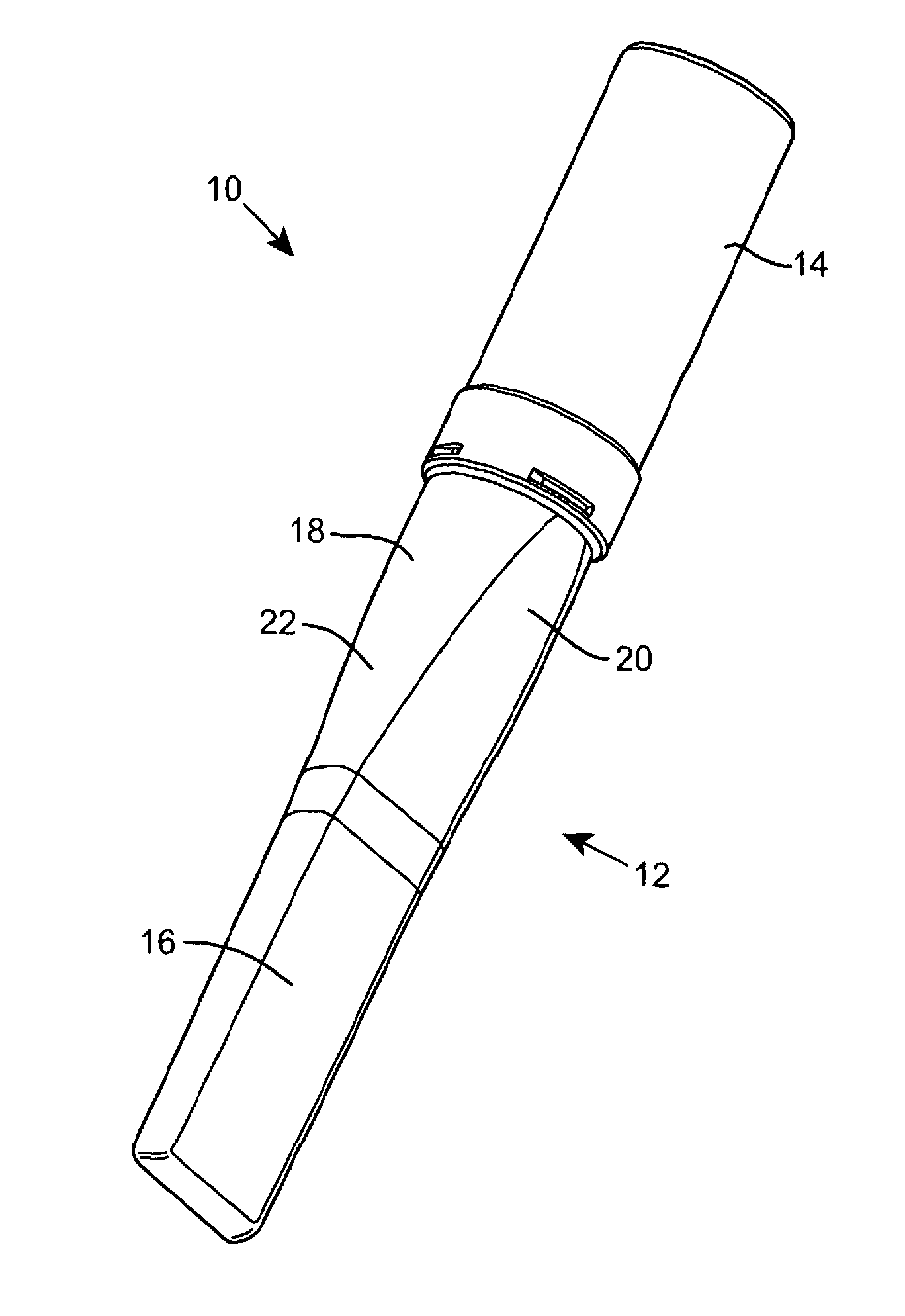
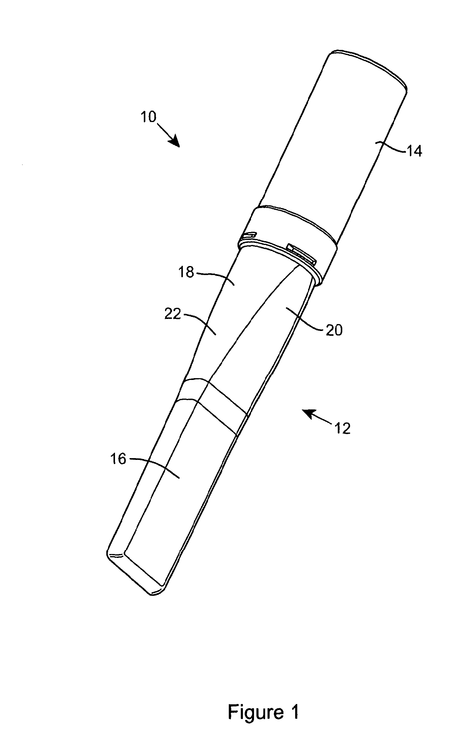
[0024]Referring firstly to FIG. 1, a chisel case is indicated generally at 10. The chisel case 10 includes a first body portion 12 and a second body portion 14 attached to the first body portion 12. The first and second body portions 12, 14, are both hollow and may be manufactured from plastics, for example recycled plastics, which provide a rigid and robust chisel case 10. The first body portion 12 has a substantially elongate box section 16 for receiving a blade of a chisel in use. Adjoining the box section 16 is a tapered transitional portion 18, which tapers outwardly in a direction away from the box section 16. The transitional portion 18 has a rectangular lateral cross-section at the end adjoining the box section 16 and a circular cross-section at the opposite end. The transitional portion 18 has a pair of opposing planar surfaces 20 adjoining a pair of opposing curved surfaces 22. The planar surfaces 20 of the transitional portion 18 also smoothly adjoin the planar surfaces o...


PUM


Abstract

A chisel case 50 includes a hollow unitary body portion 52 and a removable cap portion 54. The body portion 52 has a substantially cylindrical section 56 for receiving a chisel handle 70. A substantially elongate box section 58 adjoins and is integrally formed with the body portion 52 and in use receives a chisel blade 66. A chisel 62 is contained within the chisel case 50 and is supported by a deformable blade supporting means 64 disposed at the end of the elongate box section 58 and a deformable handle supporting means 68 disposed within the cap portion 54.

Description

[0001]The present invention relates to a chisel case and particularly, but not exclusively, to a chisel case for storing and protecting a woodworking chisel.BACKGROUND TO THE INVENTION[0002]At present, chisel cases are generally designed to hold a number of chisels, however these cases typically do not ensure that a chisel blade is comprehensively protected from damage through contact with other tools or chisels. When in transit, chisel blades can become chipped or otherwise damaged, resulting in the chisel having to be re-sharpened prior to use.[0003]It is an object of the invention to provide a chisel case which provides a secure housing for a chisel and reduces the possibility of damage to the chisel or the blade of the chisel in storage or transport.SUMMARY OF THE INVENTION[0004]According to the present invention there is provided a chisel case for housing a single chisel comprising first and second unitary hollow body portions, a deformable blade supporting means disposed withi...

Claims


Application Information

Patent Timeline
Patent Type & Authority Applications(United States)
IPC IPC(8): B65D81/05
CPCB25H3/006B65D81/107B65D81/07B26B29/025A45C11/00B65D85/20
Inventor WEBB, JOHN
Owner WEBB JOHN
Why Eureka
Try Eureka