
Method of Defining Continuous Heart Rate vs AV Delay Values and Sensed to Paced AV Delay Offset in Patients Undergoing Cardiac Resynchronization Therapy

a technology of av delay and continuous heart rate, applied in the field of physiology, can solve the problems of excessive shortening of the upper rate, av delay, reluctance to meet, etc., and achieve the effect of optimizing patient outcom

Inactive Publication Date: 2012-05-17
SHAPE MEDICAL SYST
View PDF1 Cites 0 Cited by
  • Summary
  • Abstract
  • Description
  • Claims
  • Application Information

AI Technical Summary

Benefits of technology

[0021]The present invention provides a physiologic method for determining optimal AV delay over a range of heart rates from rest to

Problems solved by technology

The status of the clinical use of a dynamic AV delay is that it has been met with reluctance by the follow-up physician since there is presently no way to assign an adequate resting AV delay.
All too often, the dynamic AV delay is set too aggressively based on the use of a linear function which shortens the time at the upper rate excessively.
In doing so, ventricular filling and stroke volume output of the heart is compromised, and gas exchange in the lungs and breathing efficiency are adversely affected.
Poor alveolar ventilation results in low oxygen and high carbon dioxide levels in the alveoli; consequently, the pulmonary capillaries constrict and the airways dilate, bringing airflow and blood flow into closer physiological match.

Method used


Image

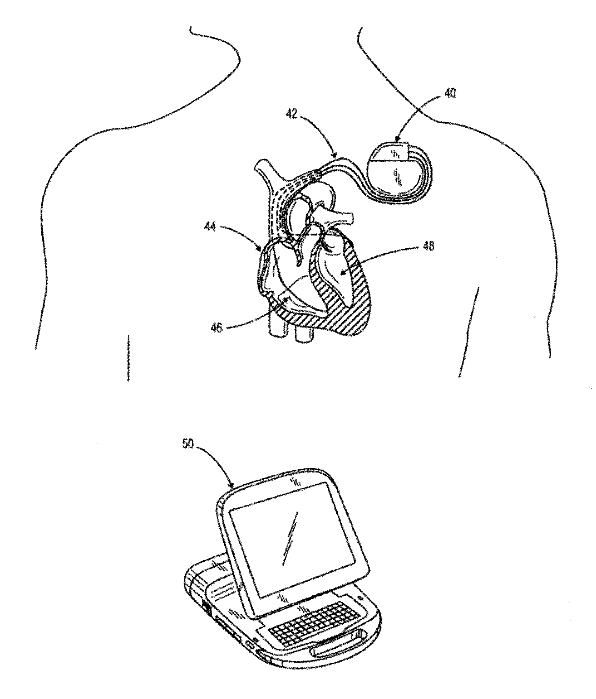
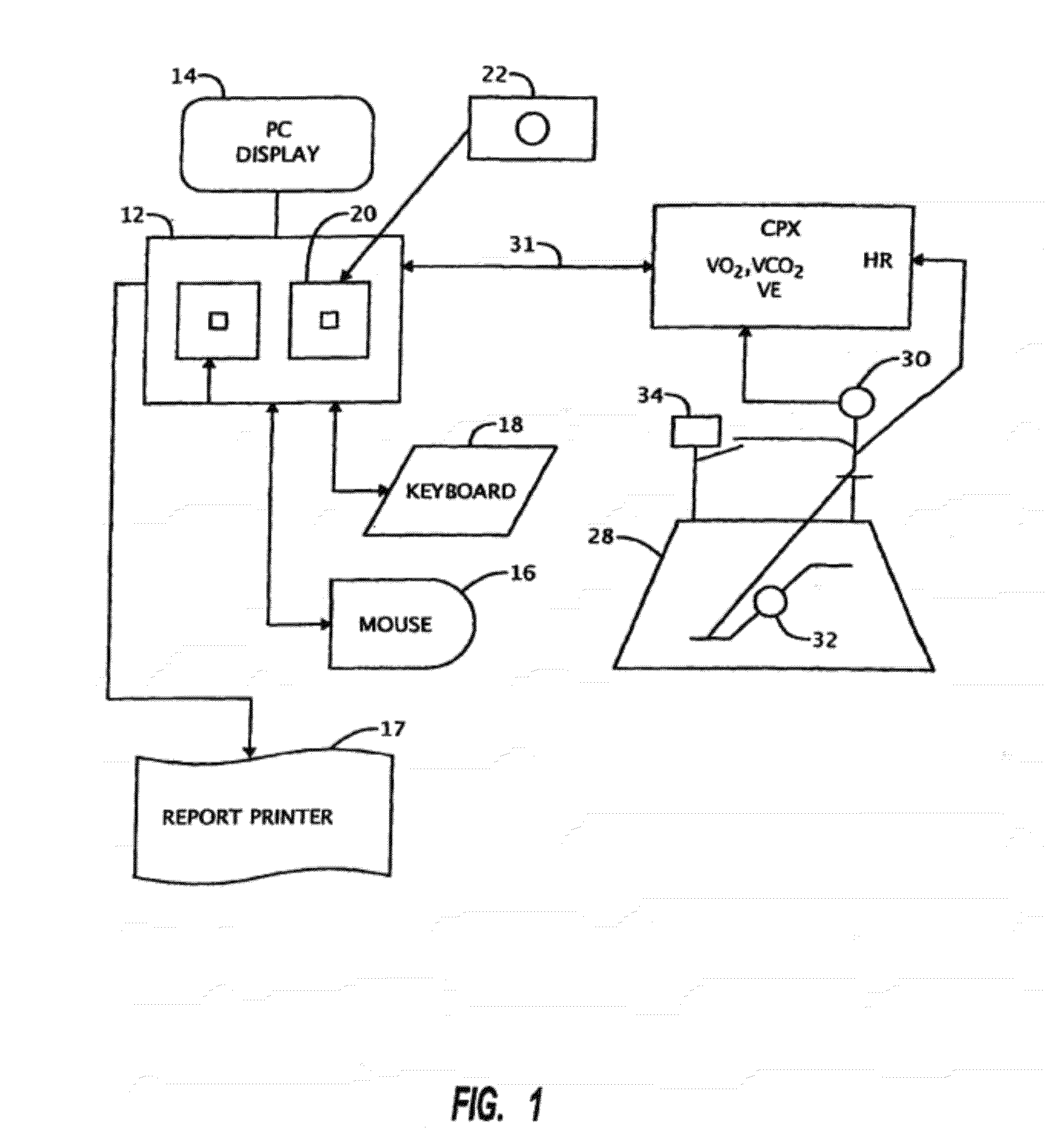
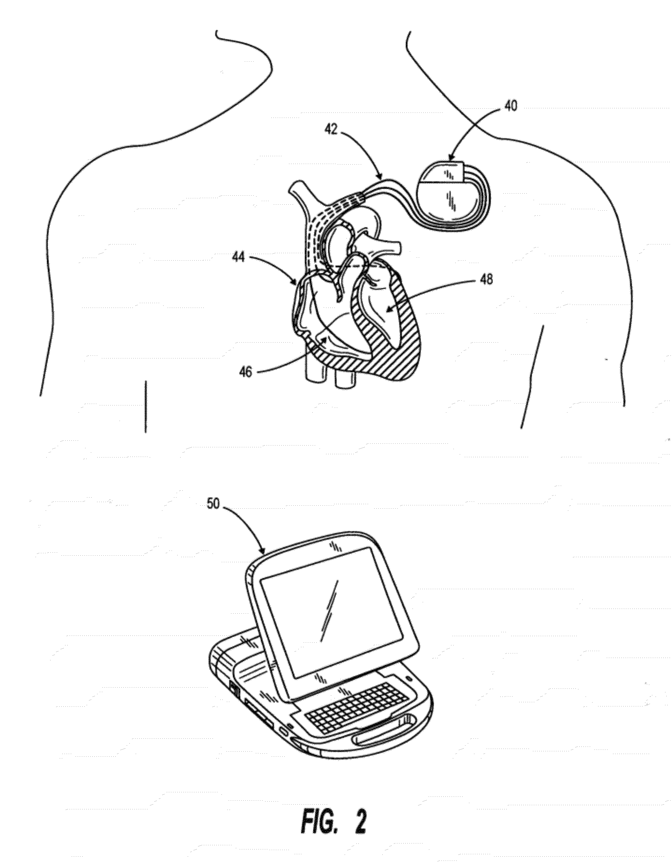
  • Method of Defining Continuous Heart Rate vs AV Delay Values and Sensed to Paced AV Delay Offset in Patients Undergoing Cardiac Resynchronization Therapy
  • Method of Defining Continuous Heart Rate vs AV Delay Values and Sensed to Paced AV Delay Offset in Patients Undergoing Cardiac Resynchronization Therapy
  • Method of Defining Continuous Heart Rate vs AV Delay Values and Sensed to Paced AV Delay Offset in Patients Undergoing Cardiac Resynchronization Therapy

Examples


Embodiment Construction

[0044]The following detailed description with respect to patient data is intended to be exemplary of a preferred method of utilizing the concepts of the present invention and is not intended to be exhaustive or limiting in any manner with respect to similar methods and additional or other steps which might occur to those skilled in the art. The following description further utilizes illustrative examples, which are believed sufficient to convey an adequate understanding of the broader concepts to those skilled in the art, and exhaustive examples are believed unnecessary.

[0045]General Considerations—The present invention is not intended to make decisions, but rather to provide information to guide the decision making process by the physician. In doing so, decisions regarding programming choices (whether one AV delay setting is better than other choices of delay setting) can be made. In some cases, the answer to these questions may be no—there is no clear reason to use one choice over...


PUM


Abstract

A method of data management for optimizing the patient outcome from the provision of cardiac resynchronization therapy (CRT) is described. A regression equation is constructed using 3 data points on a plot of AV delay vs. HR. The x-axis consist of the three points consist of resting HR, HR at the optimal AV delay value during light exercise, and the upper tracking or paced HR. The y-values associated with the three points consist of the AV delay values computed using an equation for ventricular filling time and the optimally determined AV delay value. Also described is a process for determining the sensed to paced AV delay offset. The combined processes yield 4 (the three constant values in the polynomial regression equation Y=b2X2+b1X+a and the sensed to paced AV delay offset) which can be stored on the patient's pacemaker for determining dynamically the AV delay value which is physiologically fine-tuned for each patient from resting HR to the upper tracking or paced HR. In combination with visual observation and computer-assisted ranking of the dependent variables, a physician can utilize the resulting information to render decisions on the optimal choice of the programming biventricular pacemakers / ICDs and DDDR pacemakers for individual patients.

Description

CROSS-REFERENCED TO RELATED APPLICATIONS[0001]Not applicableSTATEMENT REGARDING FEDERALLY SPONSORED RESEARCH OR DEVELOPMENT[0002]Not applicableBACKGROUND OF THE INVENTION[0003]I. Field of the Invention[0004]The present invention relates generally to the field of cardiac resynchronization therapy (CRT), and more specifically, to a physiologic method for determining optimal atrioventricular (AV) delay values over a range of heart rates from rest to the upper tracking or paced heart rate (HR) and for determining the sensed to paced AV delay offset for optimizing the patient outcome from such therapy. The disclosed method enables physicians to improve the process of programming biventricular pacemakers / ICDs and DDDR pacemakers.[0005]II. Related Art[0006]Several pacemaker manufacturers have the capability of programming a dynamic or auto-decrementing AV delay which decreases linearly from the resting programmed heart rate to the upper tracking or paced HR. The decrement range is not phys...

Claims


Application Information

Patent Timeline
IPC IPC(8): A61N1/365
CPCA61N1/3682A61N1/3627
Inventor ANDERSON, STEPHEN T.MACCARTER, DEAN J.
Owner SHAPE MEDICAL SYST
Learn More