
Energy meter

a technology of energy meters and energy information, applied in the direction of tariff meters, electric vehicles, instruments, etc., to achieve the effect of improving the way of showing energy information

Inactive Publication Date: 2012-05-24
SAIA BURGESS CONTROLS
View PDF5 Cites 0 Cited by
  • Summary
  • Abstract
  • Description
  • Claims
  • Application Information

AI Technical Summary

Benefits of technology

[0003]It is an aim of the present invention to provide for an energy meter, which has an improved way of showing the energy information.

Problems solved by technology

Interruption may for instance occur when a tenant moves out of a rented flat and the energy supplier disconnects the flat from the mains supply.

Method used


Image

  • Energy meter
  • Energy meter

Examples


Embodiment Construction

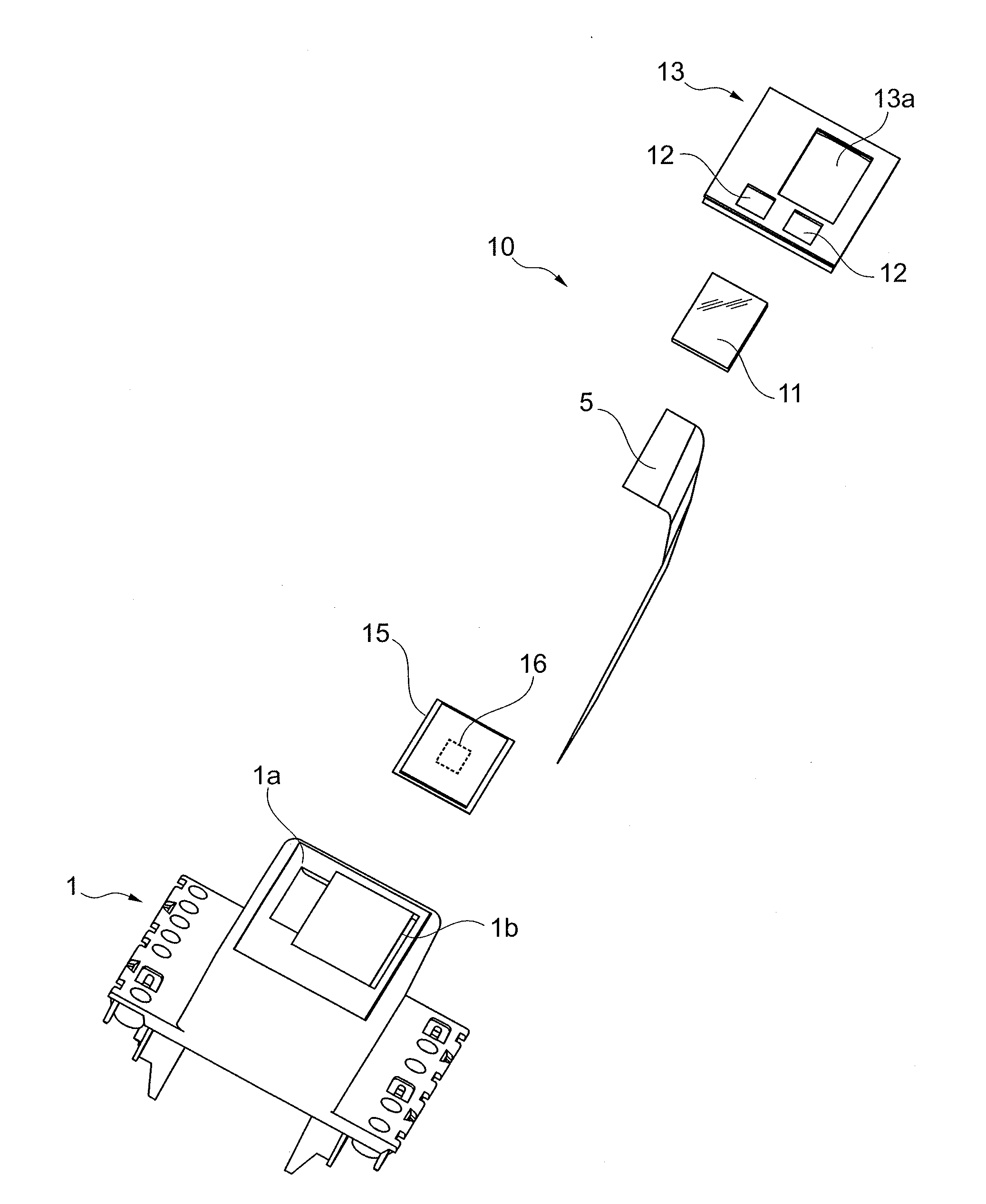
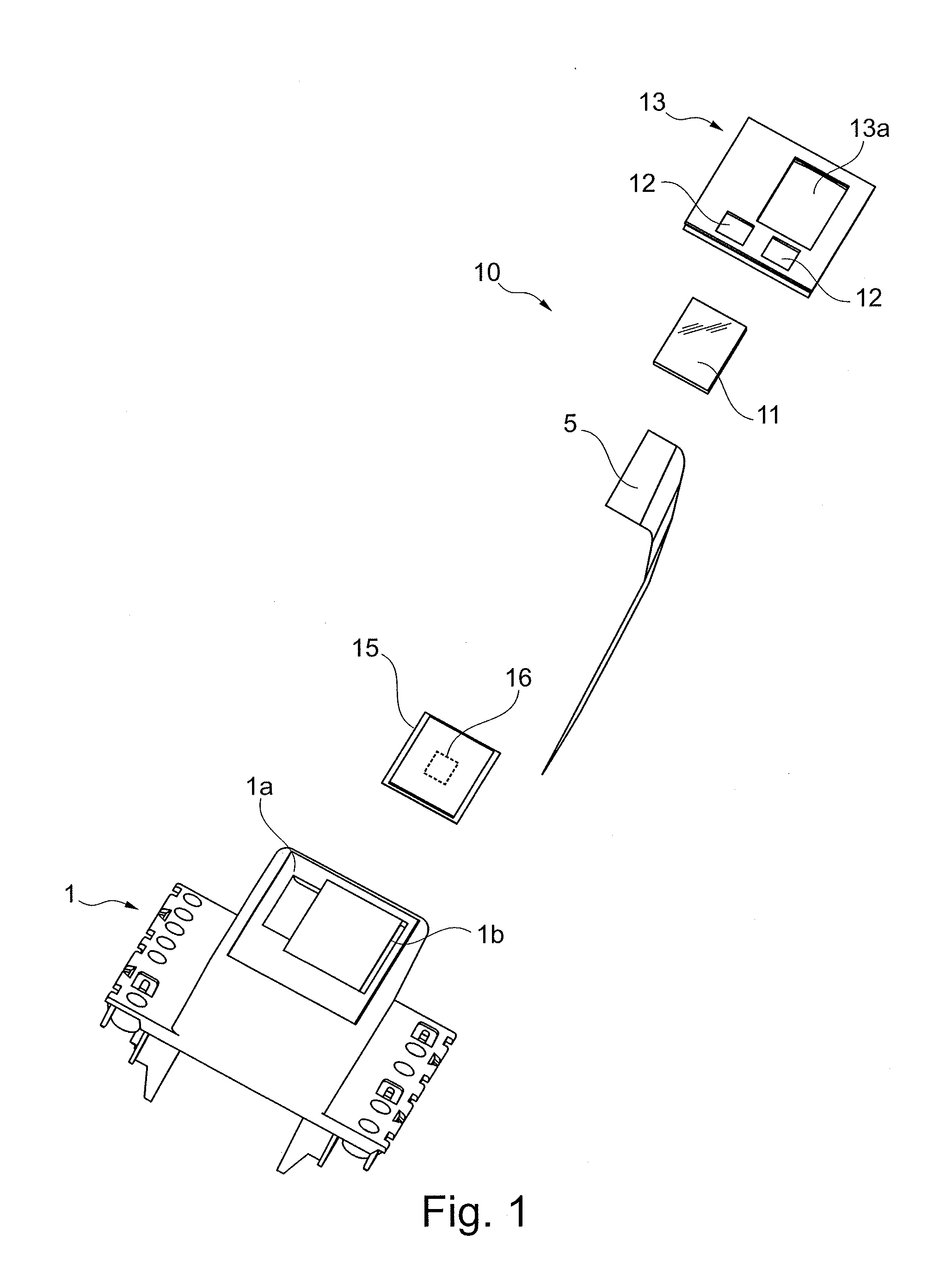
[0007]FIG. 1 shows the displaying part of an energy meter for measuring the amount of electrical energy consumed. The energy originates e. g. from the mains supply. The energy meter comprises a housing portion 1 with a front side 1a. A display assembly 10 is attached to the front side 1a and comprises a flat cable 5, an electrical display 11 and one or more buttons 12.

[0008]The cable 5 is guided through a recess 1b built in the housing portion 1 and serves for connection to the electrical circuit, which measures the amount of electrical energy consumed and which comprises e. g. a motherboard. The electrical circuit is enclosed by the housing, which the display 11 is attached to.

[0009]The display assembly 10 comprises further a plate 13 with a window 13a. The display 11 is attached to the plate 13 such that its front side is visible through the window 13a. The back side of the display 11 is connected to a printed circuit board (PCB) 15 which carries a chip 16 and to which the cable 5...


PUM


Abstract

The energy meter for measuring the amount of electrical energy consumed includes an electrical display (11) for displaying energy information corresponding to the electrical energy consumed. The display (11) is configured to change the energy information displayed by means of energy supplied by an energy source. It is configured such that when the energy supplied by the power source is interrupted the energy information displayed remains visible.

Description

FIELD OF THE INVENTION[0001]The present invention relates to an energy meter for measuring the amount of electrical energy consumed, wherein the energy meter comprises an electrical display for displaying energy information corresponding to the electrical energy consumed.BACKGROUND OF THE INVENTION[0002]Energy meters are used to measure the amount of electrical energy consumed. The electrical energy is for instance drawn from the mains supply. It is known to use an electrical display in form of an LCD or LED display to display information on the energy consumed. However, such displays are to be supplied constantly with power to display the information, even if the latter does not change. If the power is interrupted, the information is not displayed anymore. Interruption may for instance occur when a tenant moves out of a rented flat and the energy supplier disconnects the flat from the mains supply.SUMMARY OF THE INVENTION[0003]It is an aim of the present invention to provide for an...

Claims


Application Information

Patent Timeline
Patent Type & Authority Applications(United States)
IPC IPC(8): G01R21/00G01R1/02
CPCG01D4/00
Inventor COSTA, JEAN-PAUL
Owner SAIA BURGESS CONTROLS
Learn More