
Apparatus and method for mapping symbols to resources in a mobile communication system

a mobile communication system and apparatus technology, applied in the field of apparatus and method for mapping symbols of modulation symbols of harq subpackets to resources, can solve the problem that the demodulation of transmitted data packets is almost impossibl

Active Publication Date: 2012-05-24
SAMSUNG ELECTRONICS CO LTD
View PDF3 Cites 13 Cited by
  • Summary
  • Abstract
  • Description
  • Claims
  • Application Information

AI Technical Summary

Benefits of technology

This approach maximizes the resilience of data transmission by minimizing the impact of resource allocation changes in the control channel, ensuring successful demodulation of data symbols and maintaining reliable communication.

Problems solved by technology

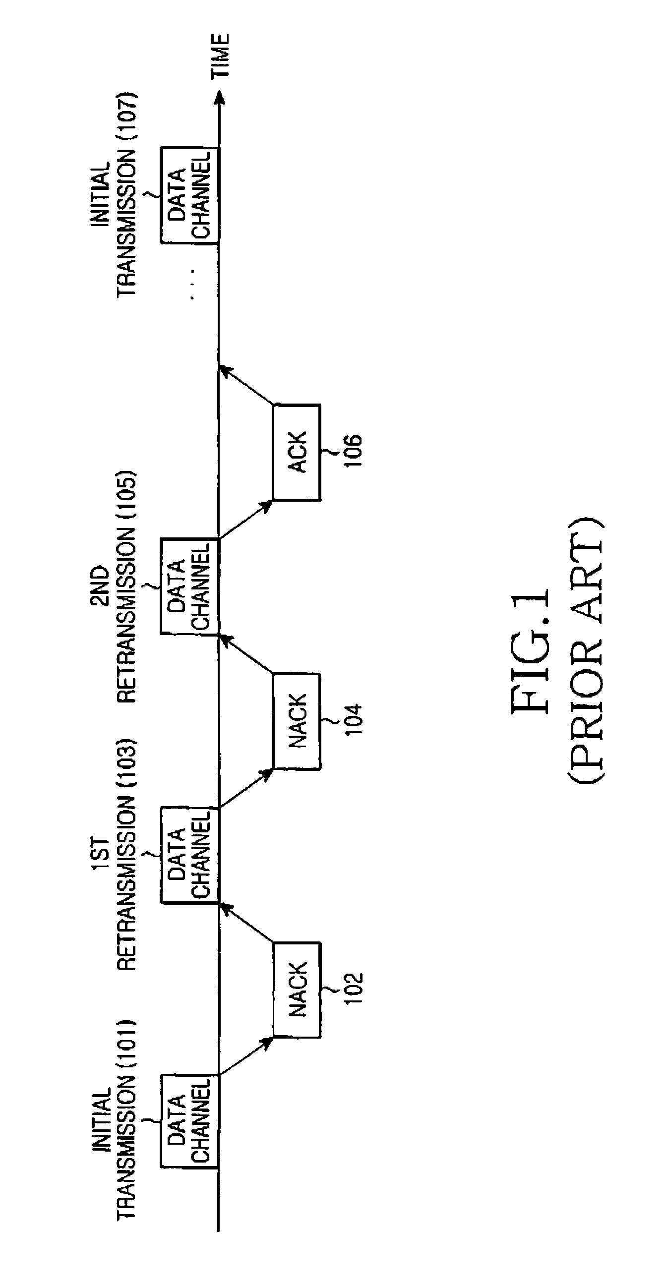
However, if there is an error in the data, the receiver feeds a Non-Acknowledgement (NACK) back to the transmitter so that the transmitter retransmits the previously transmitted packet.
Therefore, when an error occurs during reception of information on the control channel region at a terminal, demodulation on the transmitted data packet can be almost impossible.

Method used


Image

  • Apparatus and method for mapping symbols to resources in a mobile communication system
  • Apparatus and method for mapping symbols to resources in a mobile communication system
  • Apparatus and method for mapping symbols to resources in a mobile communication system

Examples


first embodiment

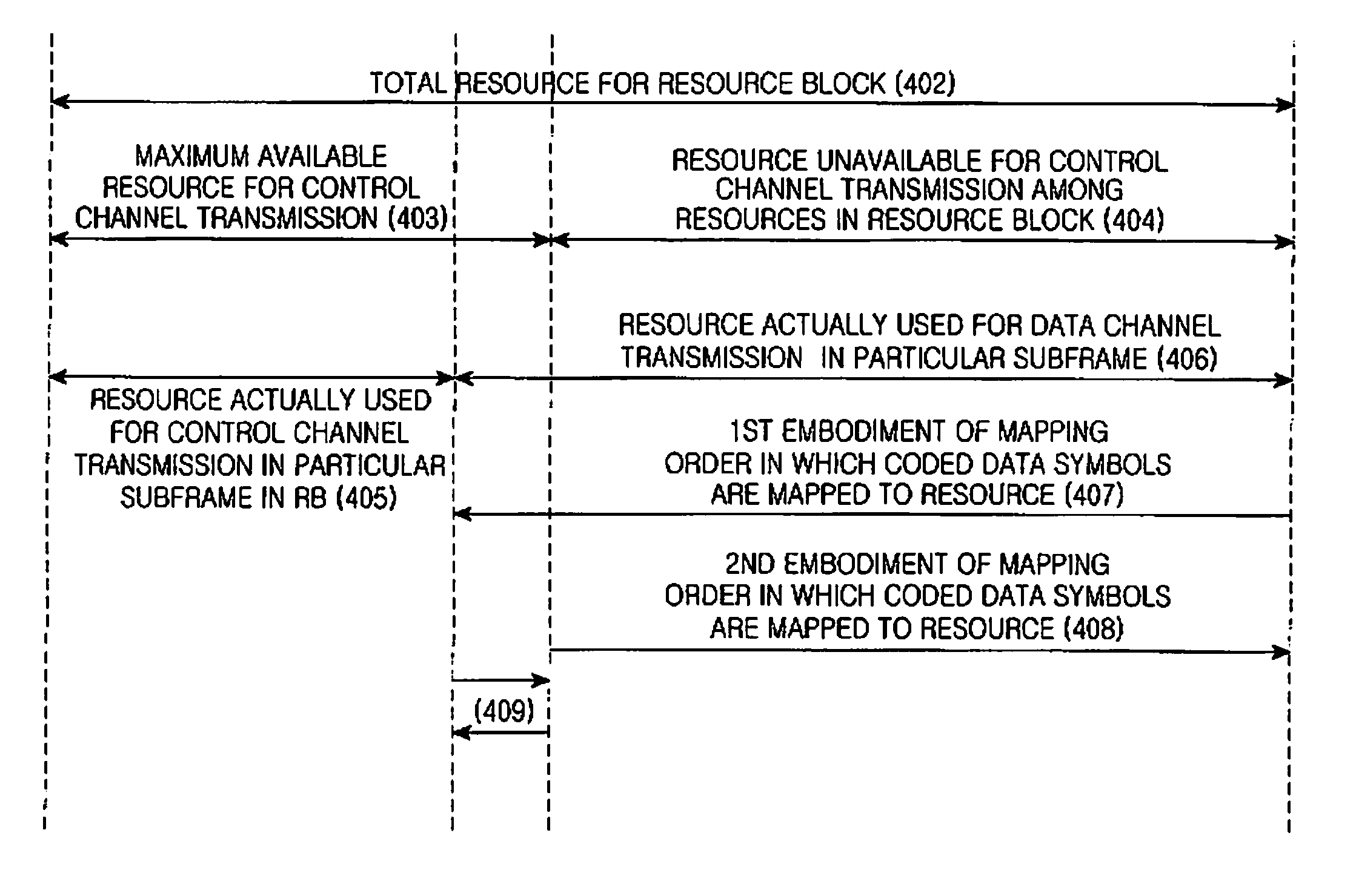
[0070]A first embodiment starts mapping the coded data symbols from the resources in the opposite side of the resources available by control channels as illustrated by reference numeral 407.

second embodiment

[0071]A second embodiment performs mapping on the coded data symbols from the next position of the maximum available resources 403 available for control channels as illustrated by reference numeral 408, and then maps the coded data symbols to the resources actually unused for control channel transmission in the corresponding subframe among the maximum available resources 403 as illustrated by reference numeral 409. As illustrated in FIG. 4, the mapping order for the resources denoted by reference numeral 409 is possible for both directions.

[0072]According to the foregoing mapping method of the present invention, the position of resources to which coded symbols of each subpacket illustrated in FIG. 2 are mapped in a resource block can maximally reduce the influence on the change in position of the resources 405 actually used for control channels in the resource block. More specifically, because the coded data symbols undergo mapping beginning from the next to the maximum available re...

fourth embodiment

[0103]FIG. 13 is a flowchart illustrating a method for generating subpackets in a communication system according to the present invention. Referring to FIG. 13, in step 1301, a transmitter and a receiver determine a reference value, or ‘L’ value, based on which data subpackets are generated, among the total number T of REs available in the allocated resource block(s) (L≦T). For example, in downlink communication, because the transmitter serves as a base station and the receiver serves as a terminal, all terminals in one base station may have the same ‘L’ value, or every terminal may have a different ‘L’ value. When all terminals have the same ‘L’ value, the ‘L’ value can be defined such that the terminals always have only the fixed ‘L’ value, or the ‘L’ value can be varied through broadcast signaling of system information. However, when every terminal has a different ‘L’ value, the ‘L’ value can be determined through predetermined signaling for each terminal. Alternatively, a ‘Defau...


PUM


Abstract

A method for transmitting data information and control information by a transmitter in a communication system is provided. The method includes identifying an amount of resources to be used for control channel transmission within a predetermined maximum amount of resources available for control channel transmission among total resources of a subframe; mapping control information onto the identified amount of resources to be used for the control channel transmission; mapping data information onto all remaining resources of the subframe, other than the identified resources used for the control channel transmission among the total resources; and transmitting information related to the amount of resources to be used for the control channel transmission, through a predetermined control channel; and transmitting the mapped control information, and the mapped data information.

Description

PRIORITY[0001]This is a continuation application of U.S. patent application Ser. No. 12 / 129,194, which claims priority under 35 U.S.C. §119(a) to a Korean Patent Application filed in the Korean Intellectual Property Office on May 29, 2007 and assigned Serial No. 2007-52333, a Korean Patent Application filed in the Korean Intellectual Property Office on May 29, 2007 and assigned Serial No. 2007-52281, a Korean Patent Application filed in the Korean Intellectual Property Office on Aug. 10, 2007 and assigned Serial No. 2007-80648, a Korean Patent Application filed in the Korean Intellectual Property Office on Sep. 12, 2007 and assigned Serial No. 2007-92755, and a Korean Patent Application filed in the Korean Intellectual Property Office on Oct. 9, 2007 and assigned Serial No. 2007-101491, the disclosures of all of which are incorporated herein by reference.BACKGROUND OF THE INVENTION[0002]1. Field of the Invention[0003]The present invention relates generally to a mobile communication ...

Claims


Application Information

Patent Timeline
Patent Type & Authority Applications(United States)
IPC IPC(8): H04L27/00
CPCH04L1/0026H04L1/1867H04L5/0007H04L5/0023H04L5/0064H04L5/0044H04L5/005H04L5/0053H04L5/003H04B7/2621H04L1/1896
Inventor KWON, HWAN-JOONHUH, YOUN-HYOUNGCHO, JOON-YOUNGLEE, JU-HOHAN, JIN-KYU
Owner SAMSUNG ELECTRONICS CO LTD
Learn More