Roller skate

a roller skate and roller technology, applied in the field of roller skates, can solve the problems of reducing the service life affecting the performance of the roller skate, and unable to solve the problems in a satisfactory manner, so as to facilitate the change of direction and reduce the clumsiness of skating

Active Publication Date: 2012-05-31
FLOW MOTION TECH AB
View PDF19 Cites 4 Cited by
  • Summary
  • Abstract
  • Description
  • Claims
  • Application Information

AI Technical Summary

Benefits of technology

[0013]The main purpose of the present invention is to at least mimic the element of balance when skating on ice and also provide muscle activation with an element of balance that is more difficult than normal ice skating can offer. A further purpose of the present invention is that the effects of fitness and speed training, which are achieved with the present design, should be transferable to skating on ice. Another purpose is to facilitate changes i

Problems solved by technology

Several months of vital practice/training are lost each year since many ice hockey players are not able to train/practice hockey on ice during the summer.
The long contact surface also makes directional changes more difficult.
None of these existing designs have thus succeeded to resolve problems in a satisfactory manner.
The main problem with all previous solutions is that these designs do not achieve the element of balance that is found when skating on ice.
Since the blade on an ice hockey skate is wholly or partly arch-shaped, contact with the ice is reduced and consequently the element of balance more difficult.
The usual inline skate frame thus provides more control because the contact area is larger, but this brings the problem of fast turns being much more difficult and it is also much harder to accelerate compared with a skate on ice.
The problem with these designs is that the skater still does not have the element of balance that he or she has on the ice.
Because the effects of fitness and speed training are mostly located to the muscles that are trained, this means that training effects from inline skating has a very low transmissibility to skating on ice, which is highly detrimental to the athletes who m

Method used


Image

  • Roller skate
  • Roller skate
  • Roller skate

Examples


Embodiment Construction

[0014]The invention will be described in greater detail below with reference to the accompanying schematic drawings that in an exemplifying purpose show the current preferred embodiments of the invention.

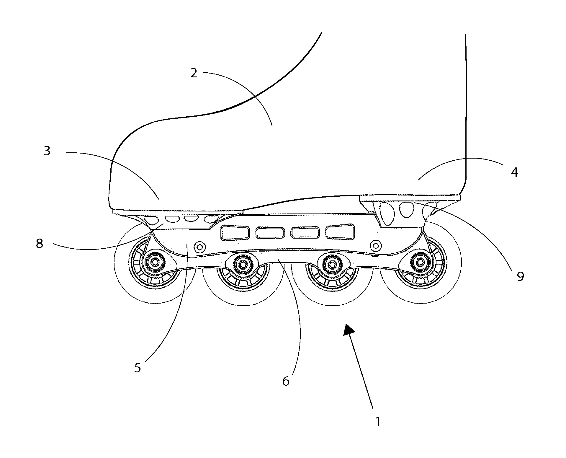
[0015]FIG. 1 shows an inline skate with an inline wheel frame in accordance with the present invention.

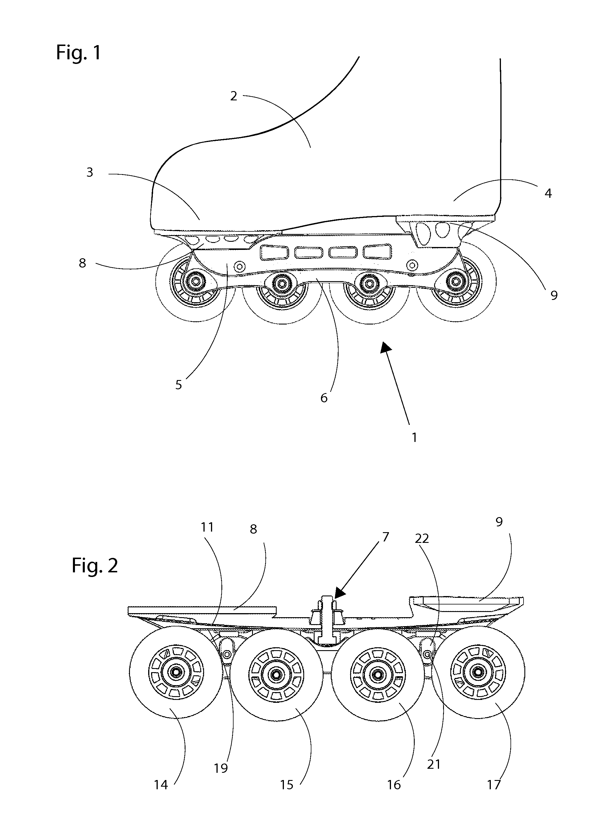
[0016]FIG. 2 shows a cross-sectional view of an inline frame in accordance with the first embodiment.

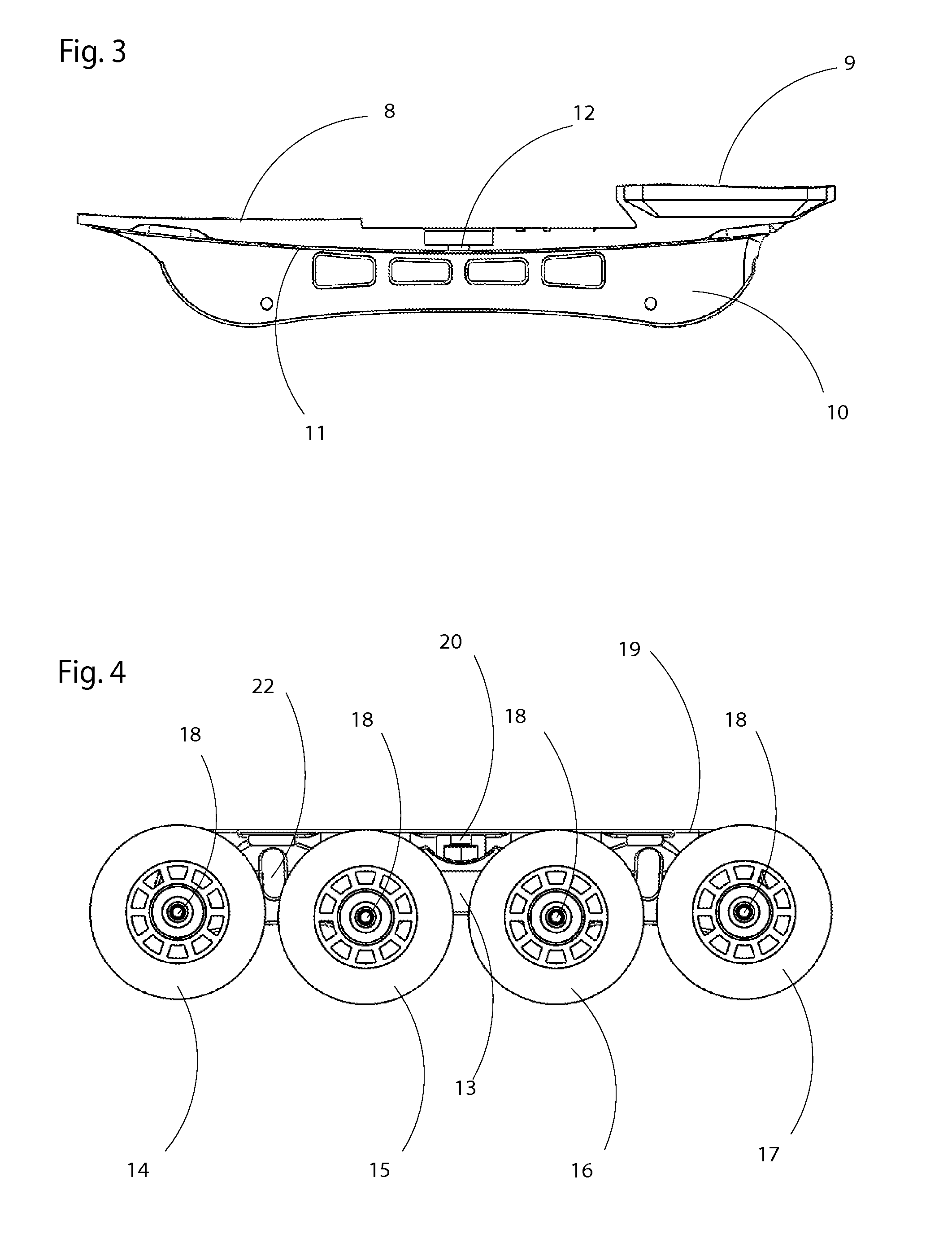
[0017]FIG. 3 shows in more detail a cross-sectional view of the upper chassis section included in the inline frame.

[0018]FIG. 4 shows in more detail a cross-sectional view of the lower chassis section included in the inline frame.

[0019]FIG. 5a-c shows the joint function in more detail.

[0020]FIG. 6a-c shows the present inline frame's function.

[0021]FIG. 7a-c shows an embodiment of the present invention.

[0022]FIG. 8a-c shows an embodiment of the present invention.

[0023]FIG. 9a shows an inline frame, and FIG. 9b is a perspective side view of a separate chassis element according to an e...


PUM


Abstract

The present invention relates to an inline frame (1) for an inline skate, designed to mimic the properties of an ice hockey skate blade on ice. The inline frame (1) includes at least one first connection part (8) intended to be connected to a boot (2) and at least two wheels positioned essentially in the inline frame's (1) longitudinal direction. The unique thing about the inline frame is that it includes an upper chassis section (5) and a lower chassis section (6) which via a coupling element (7) are arranged to be rotatable in the inline frame's (1) longitudinal direction, and that the upper chassis section (5) includes at least one first contact surface (11) and that the lower chassis section (6) includes at least one second contact surface (19), where at least one of the first contact surface and the second contact surface is curvilinear.

Description

TECHNICAL FIELD [0001]The present invention concerns a type of roller skate or similar. More specifically the present invention regards a roller skate in accordance with the claims.BACKGROUND OF THE INVENTION[0002]To become a good ice hockey player requires thousands of hours of training in how to skate and play hockey. Several months of vital practice / training are lost each year since many ice hockey players are not able to train / practice hockey on ice during the summer. An alternative solution to this problem is to skate on inline skates during the summer.[0003]The characteristics between traditional inline skate wheel frames and the blade which an ice hockey player skates with on ice differ substantially from each other.[0004]An inline skate frame has a long, flat contact plane with the underlying surface, while the blade of a skate which an ice hockey player has on the ice, is not completely flat, but is arch-shaped along all or part of its length. This means that the element of...

Claims


Application Information

Patent Timeline
IPC IPC(8): A63C17/04
CPCA63C17/065A63C17/0046A63C17/16A63C17/06A63C17/0093
Inventor MARS, PER
Owner FLOW MOTION TECH AB
Why Eureka
Try Eureka