Drawer

a technology for drawers and back walls, applied in drawers, furniture parts, domestic applications, etc., can solve the problems of reduced force transmission via back walls, increased production costs per back wall, and complex corner joints

a technology for drawers and back walls, applied in drawers, furniture parts, domestic applications, etc., can solve the problems of reduced force transmission via back walls, increased production costs per back wall, and complex corner joints

US20120133259A1Inactive Publication Date: 2012-05-31PAUL HETTICH

Image

  • Drawer
  • Drawer
  • Drawer

Examples


Embodiment Construction

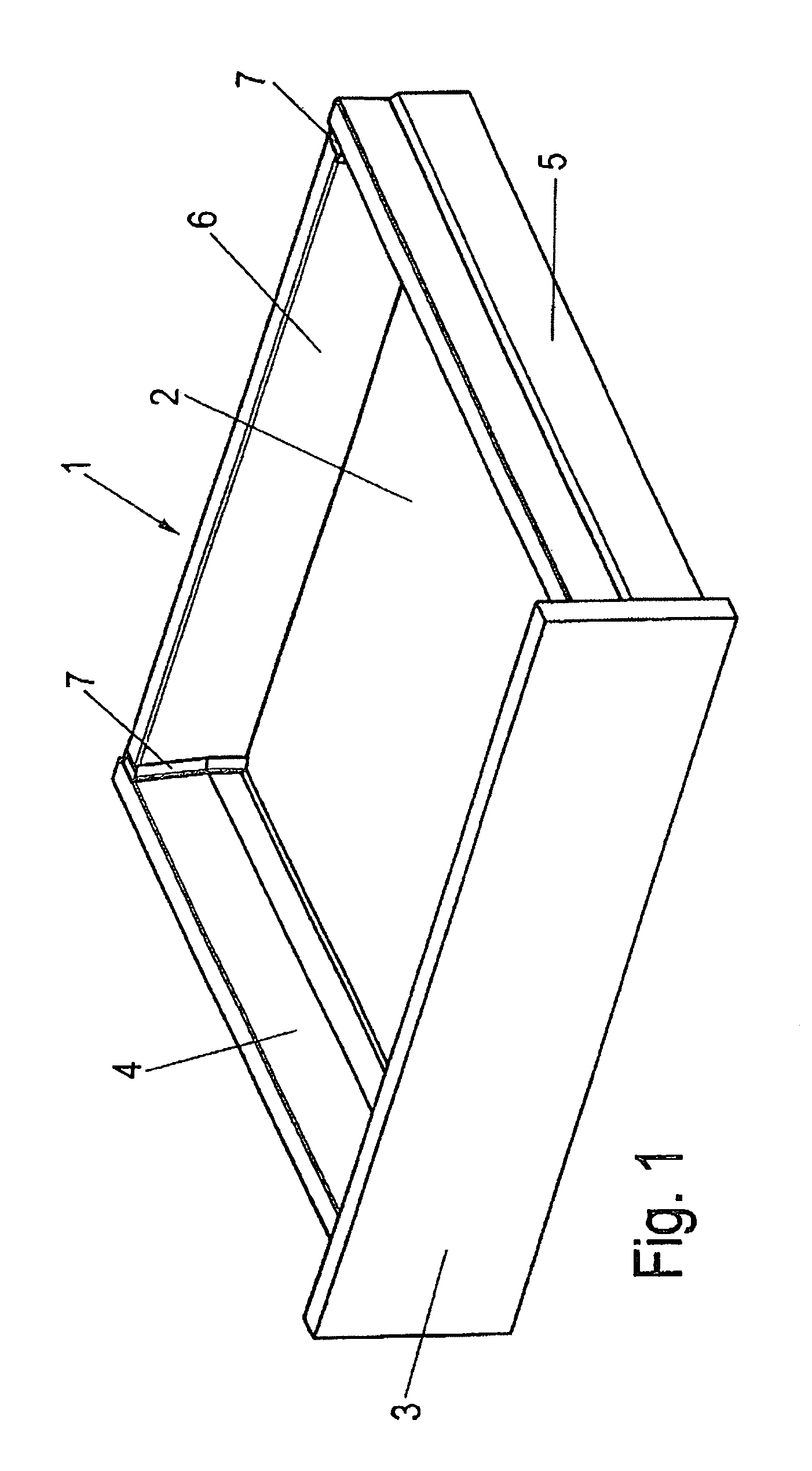
[0029]The drawer 1, shown in FIG. 1, includes a bottom part 2, a front panel 3, two lateral frames 4, 5 and a back wall 6. The back wall 6 is connected to the lateral frames 4, 5 by corner joints 7.

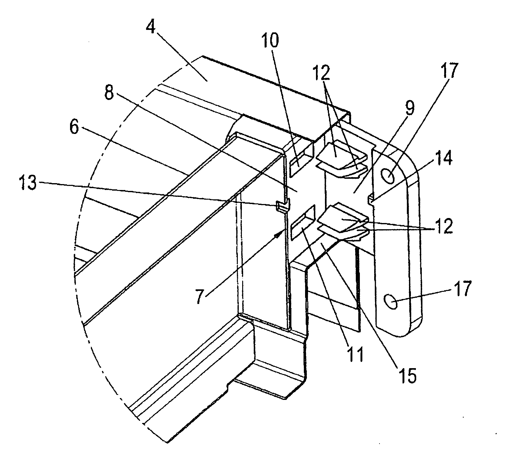
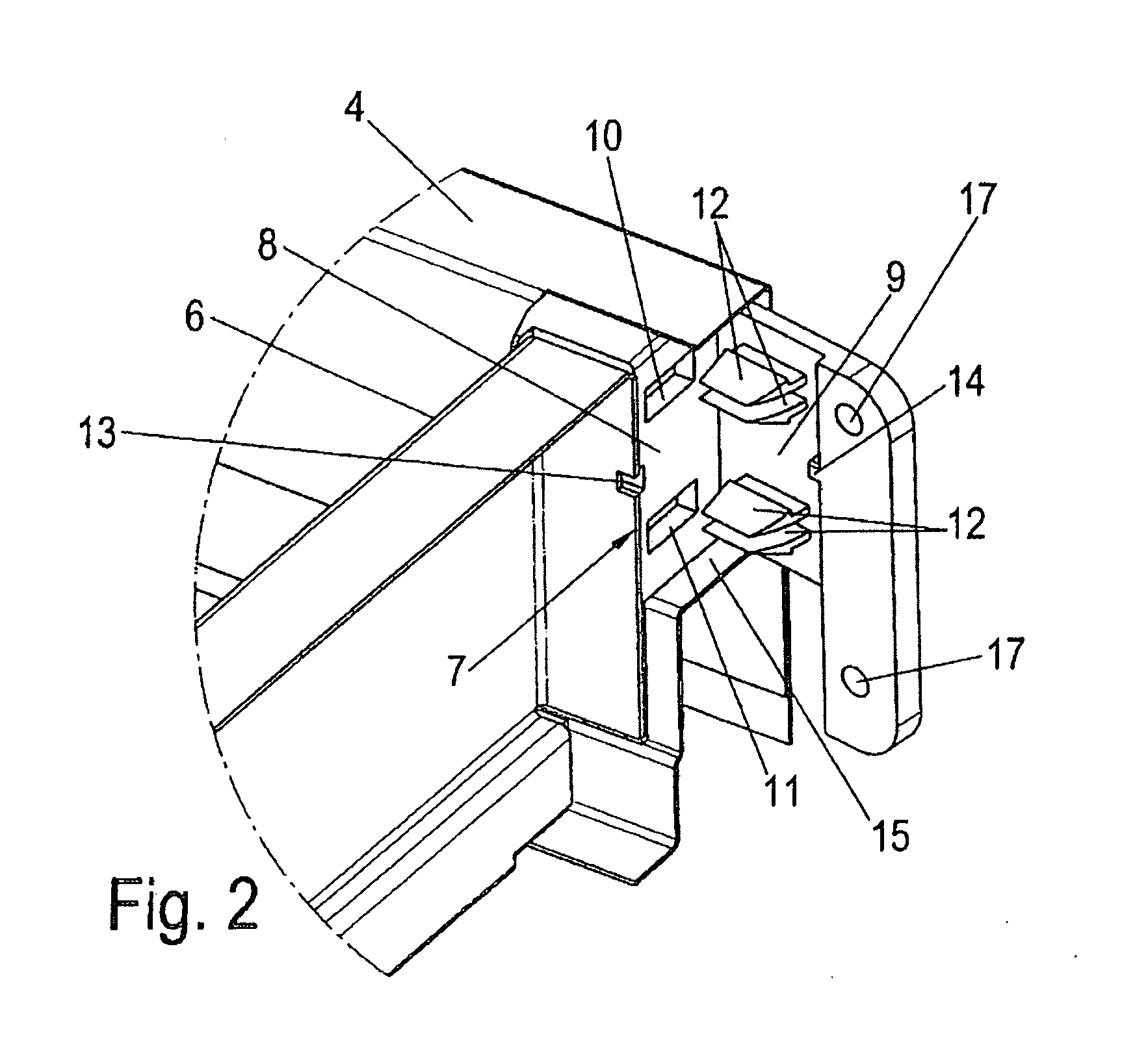
[0030]As is shown in FIGS. 2 to 6 and 8, each corner joint 7 includes a first connecting part 8 and a second connecting part 9, which parts 8, 9 are configured to be latched into one another. The two connecting parts 8, 9 are connected to one another in the manner as shown in FIGS. 6 and 8 by way of a film or living hinge 18 forming a vertical rotational axis as shown and suggested in FIGS. 2, 3 and 5. As is shown in FIGS. 5 and 6, the first connecting part 8 is arranged on a bottom side on an adapter 15 and is held by integrally arranged T-shaped pins 21 and knobs 22 acting as detent means, as shown in FIG. 8. The formation of associated recesses 19 in the adapter 15 is shown in FIG. 7. The corner joint 7 is inserted with T-shaped pins 21 in the keyhole-like recesses 19 and displaced the...


PUM


Abstract

A drawer configured to be extended from and retracted into a furniture body. The drawer includes a bottom part; a front panel; two lateral frames; and a back wall connected via a corner joint to an end region formed with one of the lateral frames. Each corner joint including a first connecting part and a second connecting part pivotably connected to the first connecting part. The second connecting part includes detent means for connecting the second connecting part to either the first connecting part or the back wall. The first connecting part is connected to an adapter associated with the end region formed by the back wall with one of the lateral frames.

Description

[0001]This application is a national stage of International Application PCT / EP2010 / 058895, filed Jun. 23, 2010, and claims benefit of and priority to German Patent Application No. 20 2009 004 982.5, filed Jul. 2, 2009, the content of which Applications are incorporated by reference herein.BACKGROUND AND SUMMARY[0002]The present disclosure relates to a drawer which can be extended from and retracted into a furniture body. The drawer includes a bottom part, a front panel, two lateral frames and a back wall which is positively or non-positively connected to the end regions formed by the lateral frames via corner joints.[0003]Such a drawer is known. In current industrially produced drawers, the lateral frames consist of hollow profile sections in which adapters are introduced for absorbing and transferring the forces to the pull-out guides. Corner joints are arranged at the end of the adapters which face the back wall. The back wall also often has to transfer forces to the lateral frame...

Claims


Application Information

Patent Timeline
31 May 2012
Publication
US20120133259A1
IPC
A47B88/04
CPC
A47B2088/0037; A47B88/0014; A47B88/941; A47B2088/902
Inventors
BABUCKE-RUNTE, GUIDO; KATHLER, ANDREAS