

Display structure
a display structure and display technology, applied in the field of display structures, can solve the problems of reducing profit, unable to reach mass manufacturing maximization as far as possible, and different molds or equipment used in the manufacture of rear casings, so as to achieve cost reduction and maximize production. the effect of the display structur
- Summary
- Abstract
- Description
- Claims
- Application Information
AI Technical Summary
Benefits of technology
Problems solved by technology
Method used
Image

Examples
first embodiment
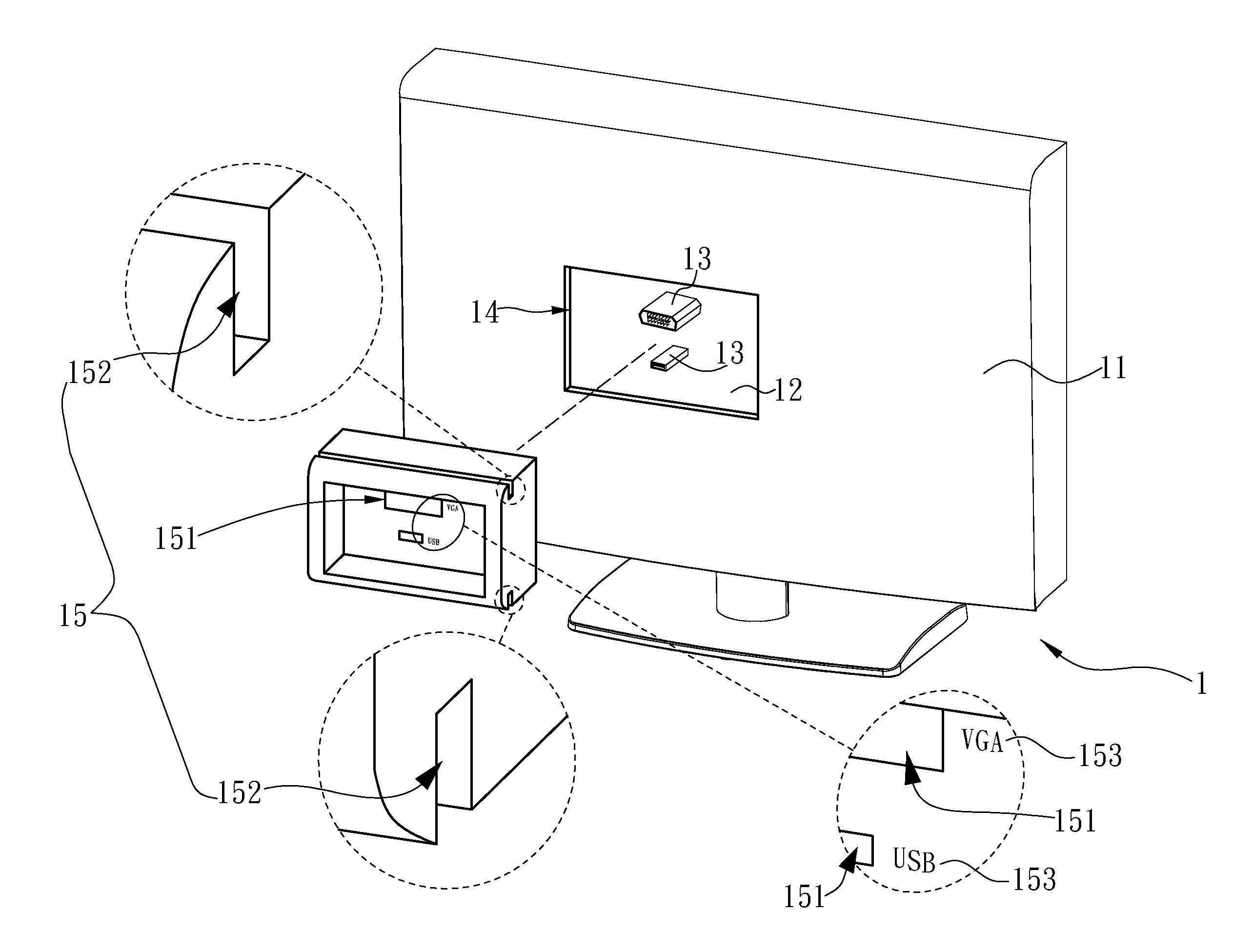
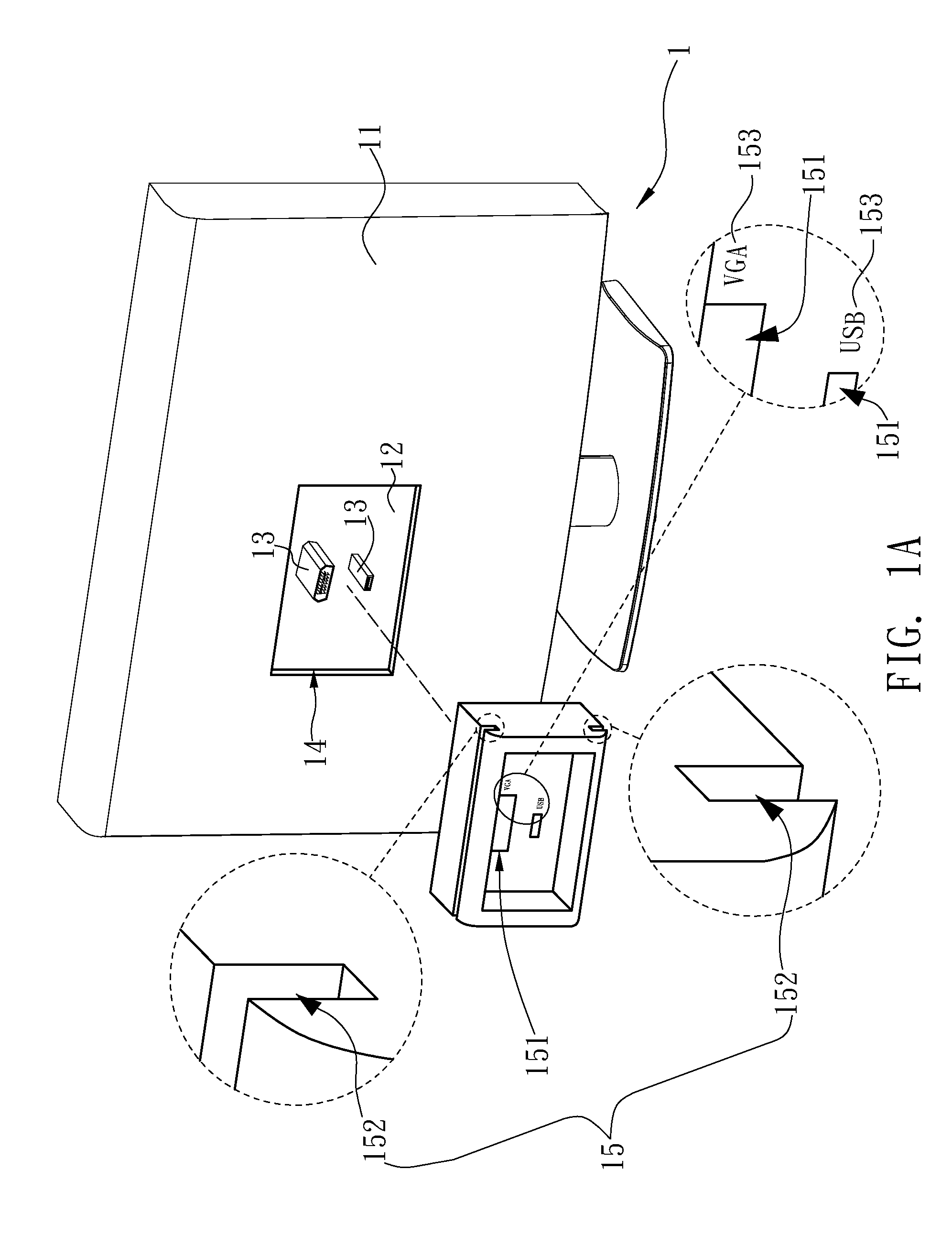
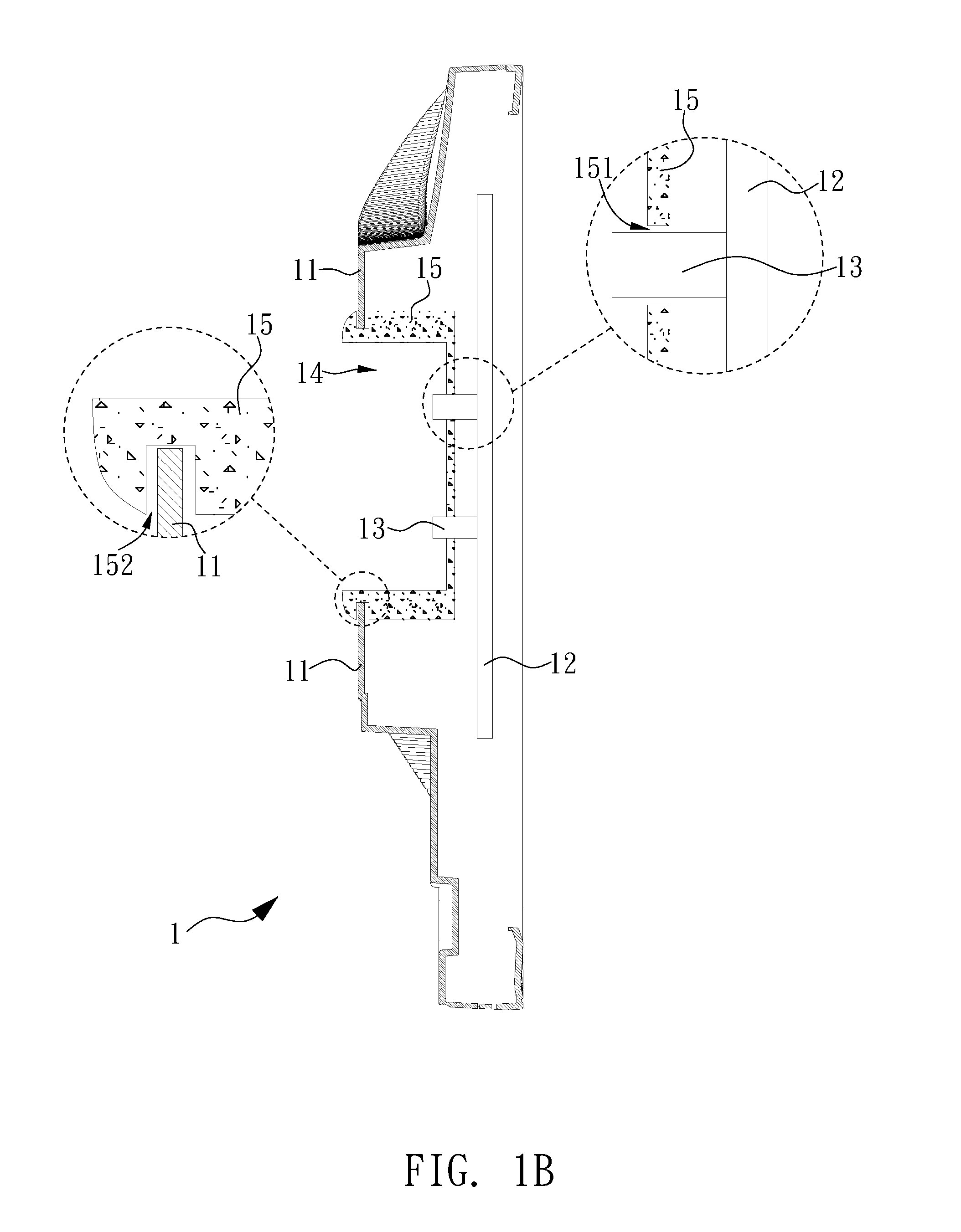
[0022]Please refer to FIG. 1A, FIG. 1A is perspective view diagram of display structure according to present invention. As shown in FIG. 1A, a display structure 1 includes a rear casing 11, a circuit board 12, two connectors 13 and a labeling unit 15. The rear casing 11 is disposed at behind of the display structure 1. The rear casing 11 is hollowed out with a casing hole 14 thereon, wherein the circuit board 12 is disposed inside the display structure 1 and two connectors 13 are disposed on the circuit board 12 so as to couple with the circuit board 12. Therefore the configuration regarding to two connectors 13 and the circuit board 12 inside the casing hole 14 can be seen from outside of the rear casing 11. The labeling unit 15 has two fitting holes 151 penetrating the labeling unit 15, and contains two notches 152 respectively disposed at upper side and lower side of the labeling unit 15. Each fitting hole 151 is corresponded to one connector 13, so that the connector 13 may be p...
second embodiment
[0026]There are some other embodiments remained. Please refer to FIG. 2, FIG. 2 is side view diagram of display structure according to present invention. As shown in FIG. 2, the rear casing 21 of display structure 2 is concave structure and the labeling unit 25 is plate structure. Two notches 212 disposing above and beneath the casing hole 24 of rear casing 21 may be corresponded to and fastened to upper side and lower side of the labeling unit 25 respectively. In some other embodiments, the labeling unit 25 might further have at least one tenon (not shown) disposed at its upper side and lower side, so that the tenon might be corresponded to and fastened to the notch 212 with tightly fit. In this manner, the mechanical strength of joint structure between the labeling unit 25 and the rear casing 21 is thus reinforced. Thus the previous advantages set forth aforementioned could also be achieved.
third embodiment
[0027]Please refer to FIG. 3, FIG. 3 is side view diagram of display structure according to present invention. As shown in FIG. 3, there is an altitude difference between upper half and lower half of the rear casing 31, therefore labeling unit 35 the display structure 3 may be L-shaped. As shown in upper enlarged diagram of FIG. 3, the labeling unit 35 has a tenon 355 disposed above, and the rear casing 31 has a notch 312 disposed at lower side and corresponded to the tenon 355. As shown in lower enlarged diagram of FIG. 3, the labeling unit 35 has a notch 352 disposed at lower side, and then the notch 352 may be corresponded to and fastened to the rear casing 31. In preferable case, the labeling unit 35 may be clockwise rotated around the notch 352 so as to be installed. In this manner, the tenon 355 above labeling unit 35 may enter the notch 312 of rear casing 31 by means of flexibility of the labeling unit 35, so as to achieve fastened and matched fashion.
PUM
 Abstract
Description
Claims
Application Information