Input/output system and devices for use with superconducting devices

a superconducting device and input/output technology, applied in superconducting magnets/coils, signal inductance without magnetic cores, computing models, etc., can solve the problems of invalidating the church-turing thesis, affecting the practical implementation of model quantum computers, and affecting the effect of ar

Active Publication Date: 2012-05-31
D WAVE SYSTEMS INC
View PDF3 Cites 32 Cited by
  • Summary
  • Abstract
  • Description
  • Claims
  • Application Information

AI Technical Summary

Benefits of technology

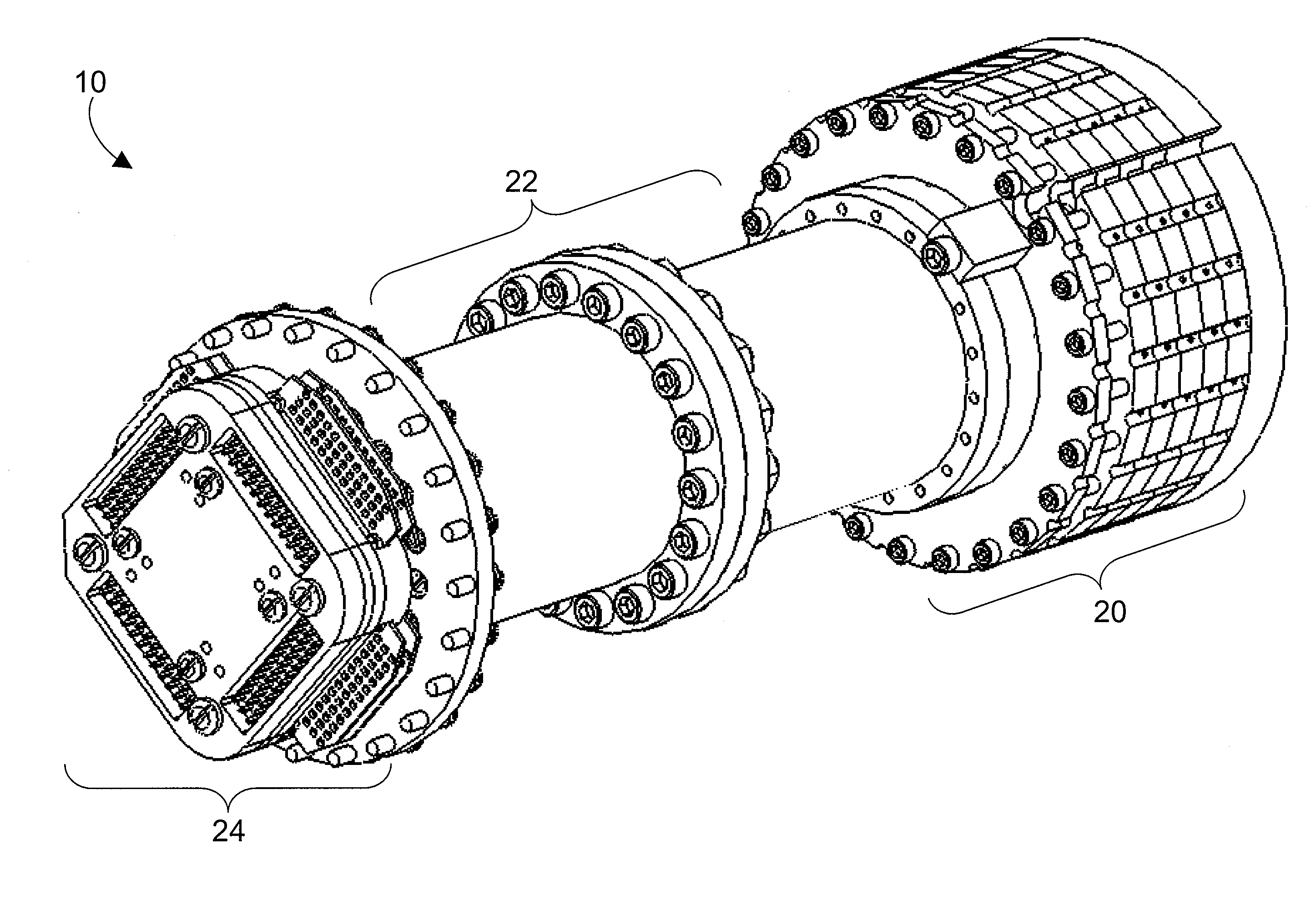
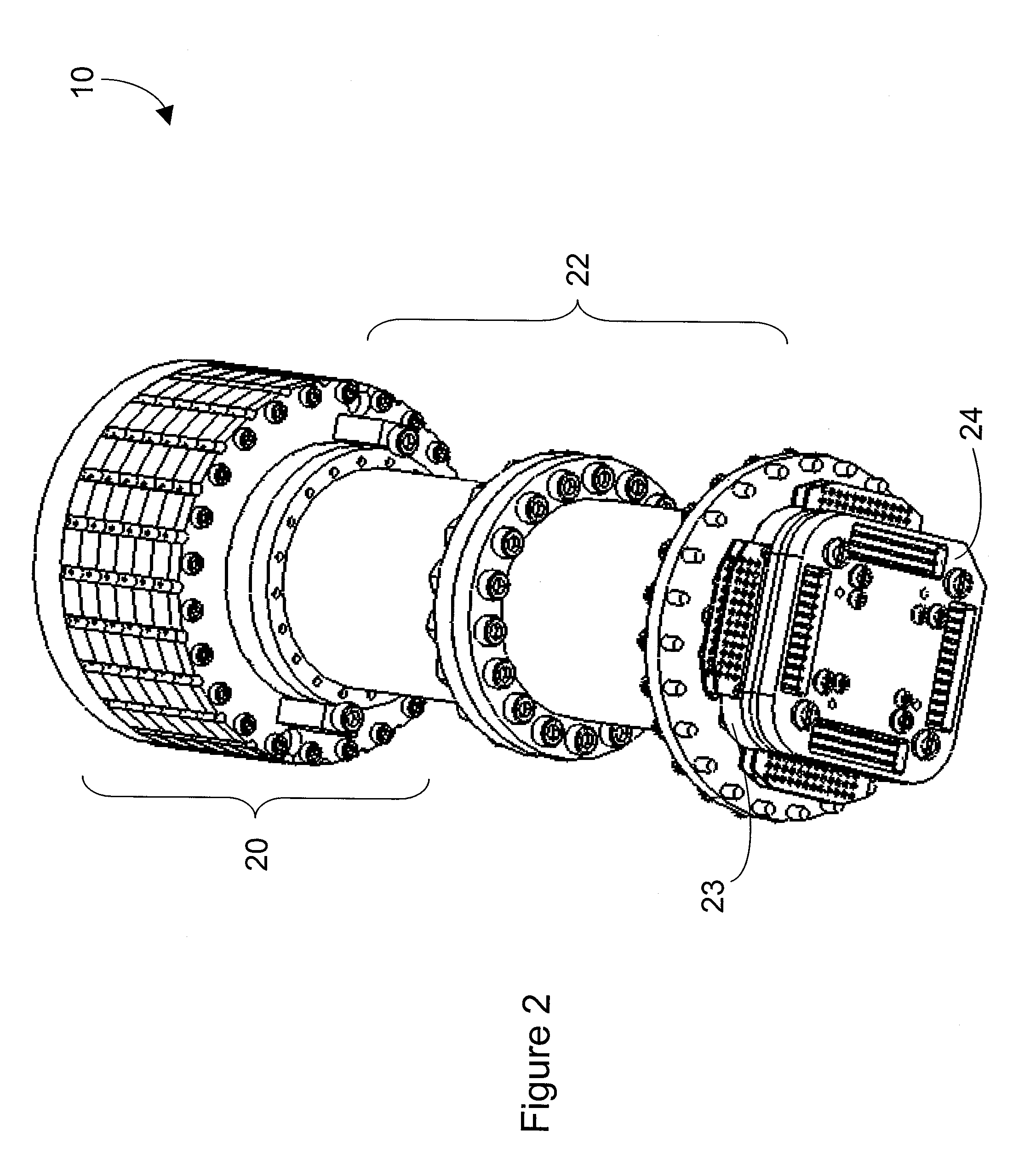
[0032]The superconducting lumped element filter assembly may further include at least one bolt that passes through both the first plate, the second plate, and the third plate, wherein the at least one bolt secures the first plate, the second plate, and the third plate as one rigid structure. The superconducting lumped element filter assembly may further include at least one additional plate including a top face, a bottom face, and an outer perimeter face, the at least one additional plate comprising a substantially non-superconducting, substantially non-magnetic material; and at least one additional plurality of superconducting lumped element filters, each of the additional plurality of superconducting lumped element filters comprising: a dielectric medium including a first face and a second face; at least one superconducting inductor; a continuous superconducting signal path that includes at least one superconducting trace on the first face of the dielectric medium, wherein the at least one superconducting inductor is superconductingly coupled in series with the continuous superconducting signal path such that the continuous superconducting signal path includes the at least one superconducting inductor; at least one capacitor coupled in parallel with the continuous superconducting signal path; and a ground plane formed by a plane of non-superconducting metal carried by the second face of the dielectric medium; wherein the dielectric medium, the at least one superconducting trace, the at least one superconducting inductor, the at least one capacitor, and the ground plane each include substantially non-magnetic materials; wherein the first plate, the second plate, the third plate, and the at least one additional plate are stacked one on top of the other to form a stack of plates, adjacent ones of the first, the second, the third, and the at least one additional plate thermally conductively connected to one another; and wherein a respective one of the first, the second, the third, and the at least one additional plurality of superconducting lumped element filters is arranged on the top face of all but one of the first, the second, the third, or the at least one additional topmost plate in the stack of plates. The superconducting lumped element filter assembly may further include at least one bolt that passes through each of the first, the second, the third, and the at least one additional plate in the stack of plates to secure the stack of plates such that each of the first, the second, the third, and the at least one additional plate is held in physical contact with at least an adjacent one of the first, the second, the third, and the at least one additional plate.
[0033]At least one embodiment may be summarized as a metal powder filter assembly including a first portion of a substantially non-superconducting, substantially non-magnetic metal, wherein the first portion has a first end, a second end, and a plurality of longitudinal passages that span between the first end and the second end of the first portion; a plurality of conductive wires, each of which is superconducting below a critical temperature, wherein each of the longitudinal passages of the first portion receives at least one conductive wire; an epoxy mixture comprising an epoxy and a metal powder that is substantially non-superconducting and substantially non-magnetic, wherein each of the plurality of longitudinal passages in the first portion is filled with the epoxy mixture and each of the plurality of conductive wires is secured in place by the epoxy mixture inside a respective one of the longitudinal passages in the first portion; and at least one common flange that encloses the plurality of longitudinal passages at least proximate at least one of the first end and the second end of the first portion. At least one conductive wire may include a wound intermediate section that is at least partially contained within a respective one of the longitudinal passages in the first portion, and wherein a longitudinal axis of the wound intermediate section is coaxially aligned with a longitudinal axis of the respective longitudinal passage. The metal powder may include at least one of copper and brass. A ratio of the epoxy mixture may be selected from the group consisting of: approximately two to one by weight of metal powder to epoxy, approximately four to one by weight of metal powder to epoxy, and approximately eight to one by weight of metal powder to epoxy.

Problems solved by technology

In 1981 Richard P. Feynman proposed that quantum computers could be used to solve certain computational problems more efficiently than a UTM and therefore invalidate the Church-Turing thesis.
Circuit model quantum computers have several serious barriers to practical implementation.
The art is still hampered by an inability to increase the coherence of qubits to acceptable levels for designing and operating practical circuit model quantum computers.
Maintaining superconducting temperatures may be difficult since many materials that are capable of superconducting do not provide good thermally conductive paths.
Such may be particularly difficult with I / O systems since such I / O systems interface with non-refrigerated environments.
Such difficulties are compounded where the structure is also to provide for the easy placement and removal of a superconducting processor.

Method used


Image

  • Input/output system and devices for use with superconducting devices
  • Input/output system and devices for use with superconducting devices
  • Input/output system and devices for use with superconducting devices

Examples


Embodiment Construction

[0089]In the following description, some specific details are included to provide a thorough understanding of various disclosed embodiments. One skilled in the relevant art, however, will recognize that embodiments may be practiced without one or more of these specific details, or with other methods, components, materials, etc. In other instances, well-known structures associated with superconducting processors, such as superconducting devices, coupling devices, and control systems including microprocessors and drive circuitry have not been shown or described in detail to avoid unnecessarily obscuring descriptions of the embodiments of the systems, devices, and methods.

[0090]Unless the context requires otherwise, throughout the specification and claims which follow, the word “comprise” and variations thereof, such as, “comprises” and “comprising” are to be construed in an open, inclusive sense, that is as “including, but not limited to.”

[0091]Reference throughout this specification ...


PUM


Abstract

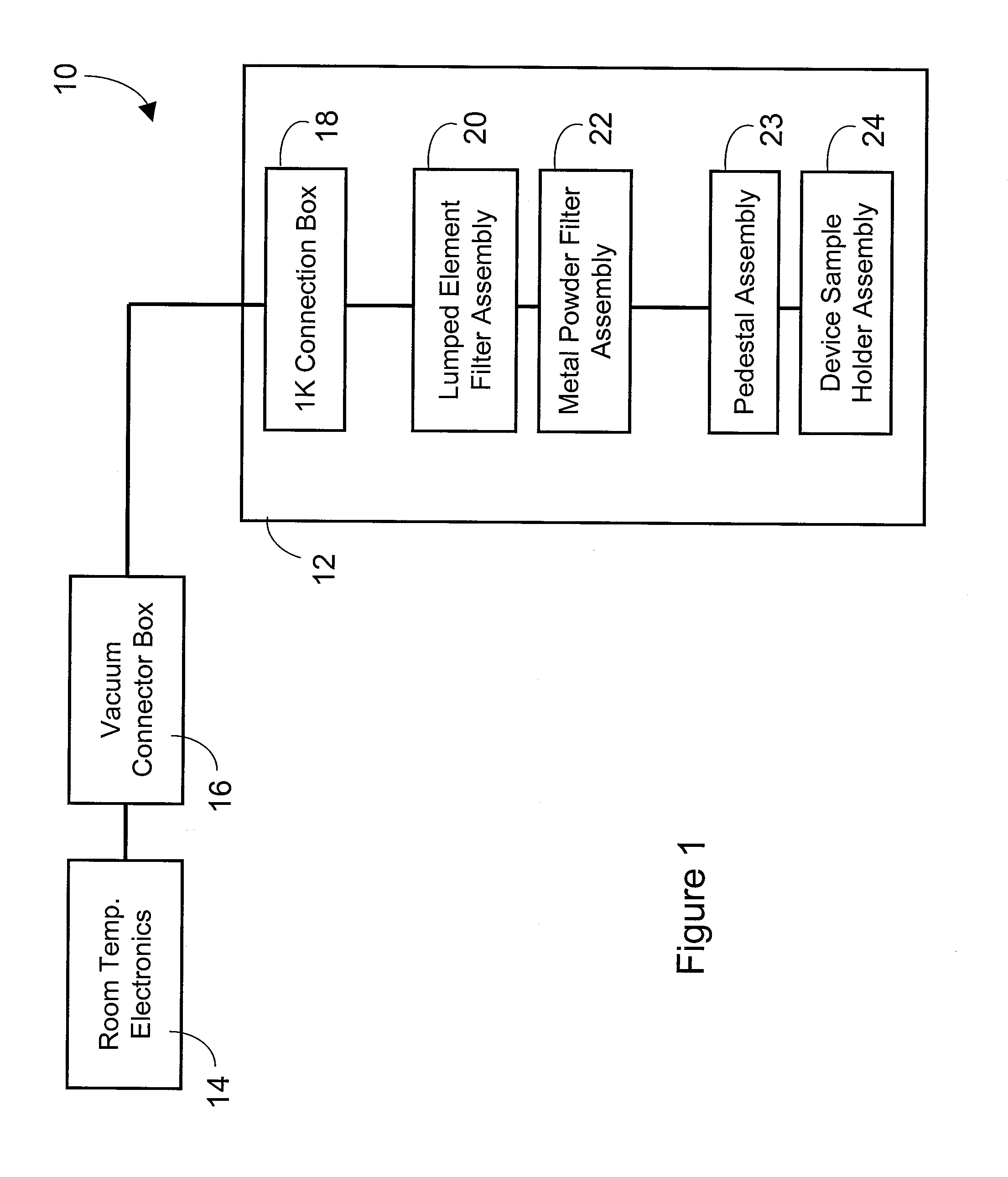
An I/O system and device for use with superconducting device provides multi-stage filtering using superconducting electrical pathways, while providing good thermal conductivity to maintain low temperature of the various components and allowing the easy mounting and dismounting of a device sample from a refrigerated environment. Filtering may include a lumped element filter assembly including multiple plates each carrying a number of lumped element filters. Filtering may include a metal powder filter assembly including multiple metal power filters formed in passages of a substantially non-magnetic portions. A device sample holder assembly secures a device sample, for example a superconducting quantum processor, and provides signals, ground and good thermal conduction.

Description

CROSS REFERENCE TO RELATED APPLICATIONS[0001]This application claims benefit under 35 U.S.C. §119(e) of U.S. provisional patent application Ser. No. 60 / 881,358, filed Jan. 18, 2007, which is incorporated herein by reference in its entirety.BACKGROUND[0002]1. Field[0003]This disclosure generally relates to input / output (I / O) systems and devices for use with superconducting devices, and particularly relates to I / O systems for use with superconducting-based computing systems.[0004]2. Description of the Related Art[0005]A Turing machine is a theoretical computing system, described in 1936 by Alan Turing. A Turing machine that can efficiently simulate any other Turing machine is called a Universal Turing Machine (UTM). The Church-Turing thesis states that any practical computing model has either the equivalent or a subset of the capabilities of a UTM.[0006]A quantum computer is any physical system that harnesses one or more quantum effects to perform a computation. A quantum computer tha...

Claims


Application Information

Patent Timeline
Patent Type & Authority Applications(United States)
IPC IPC(8): H03H7/01H01L39/02H05K7/20G06N99/00
CPCH01F6/06H01F17/02H03H7/0115H01P1/2056H01P1/202
Inventor THOM, MURRAY C.BERKLEY, ANDREWTCACIUC, ALEXANDER M.JOHNSON, MARKBUNYK, PAULCHUNG, JASPAULPETROFF, JACOB CRAIGCIOTA, FLORIN
Owner D WAVE SYSTEMS INC
Why Eureka
Try Eureka