Dual Fan Sprayer

a sprayer and fan technology, applied in the field of agricultural equipment, can solve the problems of unfavorable atomization of background foliage and uneven dispersion, and achieve the effect of preventing the delivery of atomized material

Inactive Publication Date: 2012-06-07
VANDIKE MARIO
View PDF3 Cites 3 Cited by
  • Summary
  • Abstract
  • Description
  • Claims
  • Application Information

AI Technical Summary

Problems solved by technology

This has cause random dispersion of the droplets, or particles in the case of orchards, resulting in uneven dispersion.
It is a further problem that the high velocity application...

Method used


Image

  • Dual Fan Sprayer
  • Dual Fan Sprayer
  • Dual Fan Sprayer

Examples


Embodiment Construction

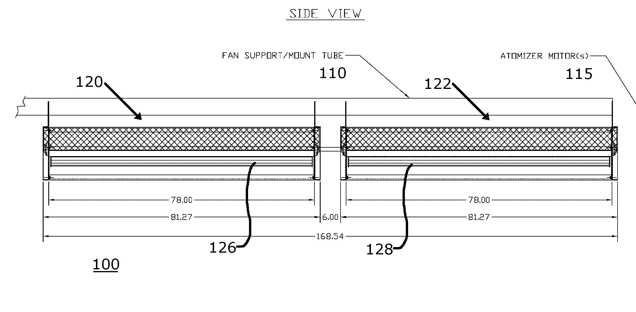
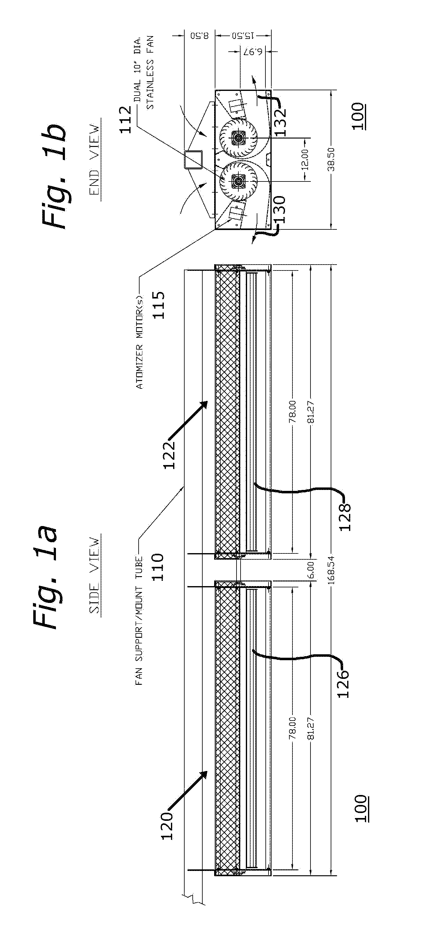
[0019]FIGS. 1a and 1b are simplified schematic side and end representations, respectively, of a 10″ diameter dual stainless steel atomizer sprayer fan arrangement 100 constructed in accordance with the principles of the invention. As shown in FIG. 1a, a fan support tube 110 contains therewithin a pair of stainless steel fans 112, the stainless steel fans being shown in an end view in FIG. 1b.

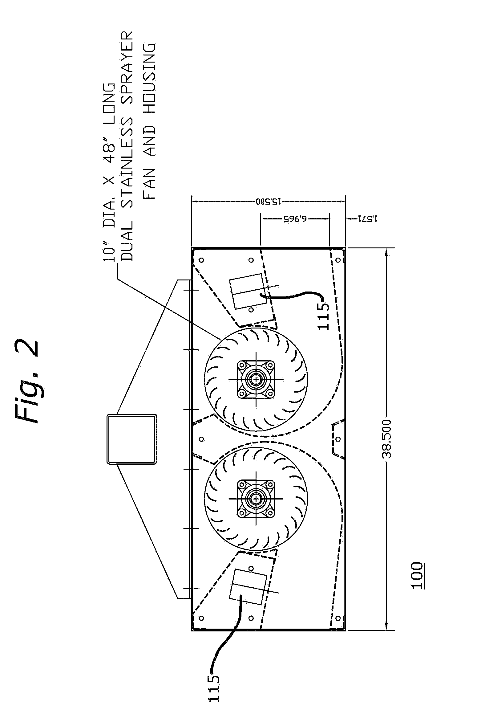
[0020]FIG. 2 is an enlargement of the simplified schematic end representation of FIG. 1b, and shows the components thereof with greater clarity. The specific illustrative embodiment of the invention shown in FIGS. 1a, 1b, and 2 is dimensioned to have an overall length of approximately 168.54″, and is comprised of a first and second sections 120 and 122, each having an overall length of approximately 81.27″. Fans 126 and 128 are themselves 78″ in length, and the first and second sections have, in this specific illustrative embodiment of the invention, a 6″ spacing is provided between their axes....


PUM


Abstract

A spray unit and process for controlled droplet atomization for use particularly in an orchard, wherein air is urged under pressure in substantially opposite directions in response to the actuation of dual, counter-rotating fans. The fans are, in one embodiment, driven by a motor that is coupled to the fans by a serpentine belt. The flowing air receives droplets of material to be substantially atomized from one or more motor-powered atomizers. The spray unit is easily retrofitted to be installed on a convention sprayer cart or tractor-pulled trailer.

Description

BACKGROUND OF THE INVENTION[0001]1. Field of the Invention[0002]This invention relates generally to agricultural equipment, and more particularly, to a sprayer arrangement that is particularly suited for use in an orchard.[0003]2. Description of the Related Art[0004]The prior art has employed a wide variety of high velocity fans, turbines, air nozzles, and the like for blowing air transversely across or through the plane of droplet generated by controlled droplet atomizers. This has cause random dispersion of the droplets, or particles in the case of orchards, resulting in uneven dispersion. It is a further problem that the high velocity application of active ingredient has resulted in masking of the atomized stream by foreground foliage, and this has further prevented the delivery of the atomized material to background foliage.[0005]It is, therefore, an object of this invention to provide a sprayer arrangement that delivers atomized material uniformly to background foliage, as w...

Claims


Application Information

Patent Timeline
IPC IPC(8): B05B9/06
CPCA01M7/0014
Inventor VANDYKE, MARIO
Owner VANDIKE MARIO
Why Eureka
Try Eureka