System and method for marking discrepancies in image of object

a technology of image discrepancies and marking methods, applied in the field of image processing technologies, can solve the problems of time-consuming and costly

Inactive Publication Date: 2012-06-07
WARECONN TECH SERVICE (TIANJIN) CO LTD
View PDF1 Cites 9 Cited by
  • Summary
  • Abstract
  • Description
  • Claims
  • Application Information

AI Technical Summary

Problems solved by technology

In general, an iteration method is usually used to inspect any discrepancies

Method used


Image

  • System and method for marking discrepancies in image of object
  • System and method for marking discrepancies in image of object
  • System and method for marking discrepancies in image of object

Examples


Embodiment Construction

[0008]The present disclosure, including the accompanying drawings, is illustrated by way of examples and not by way of limitation. It should be noted that references to “an” or “one” embodiment in this disclosure are not necessarily to the same embodiment, and such references mean at least one.

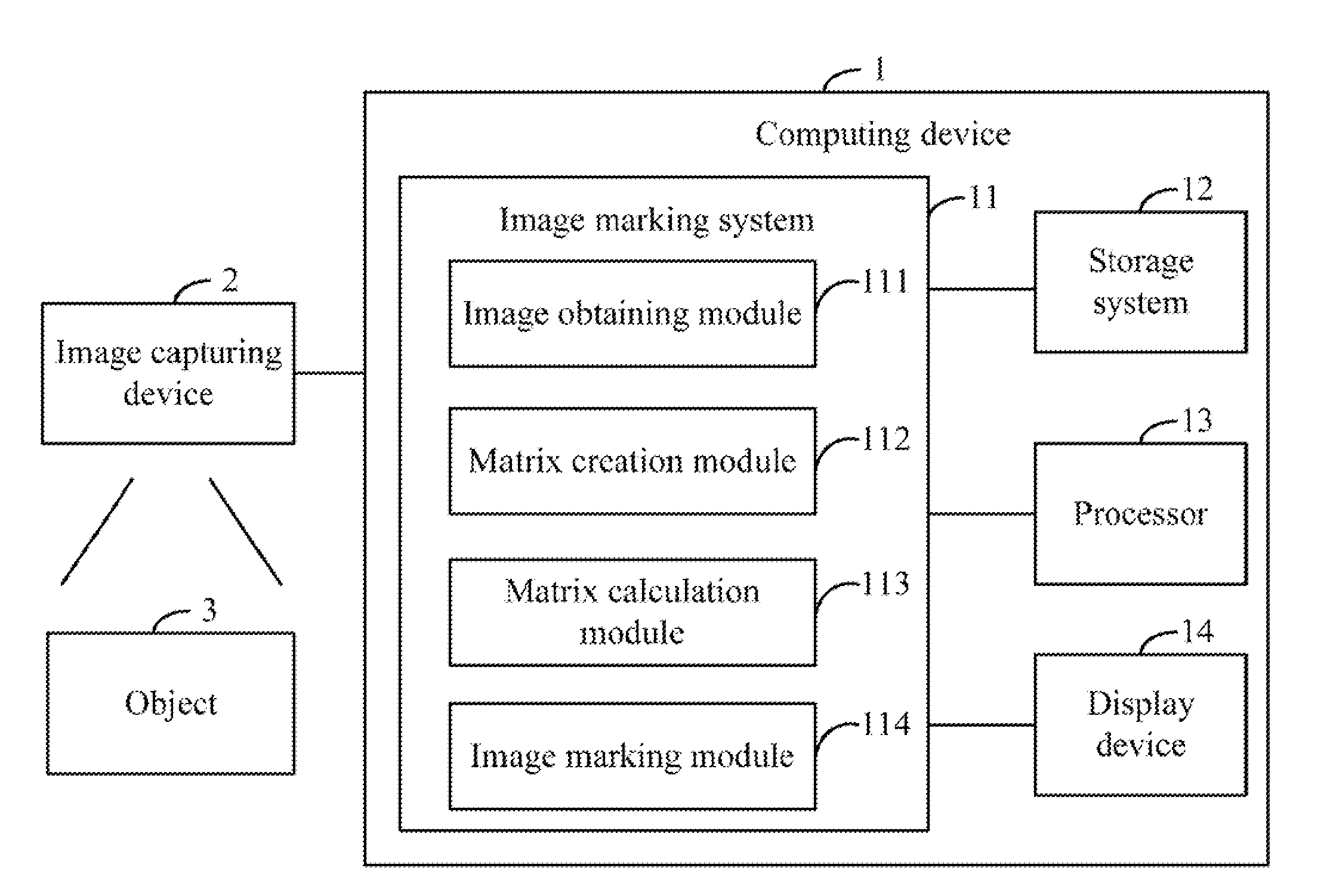
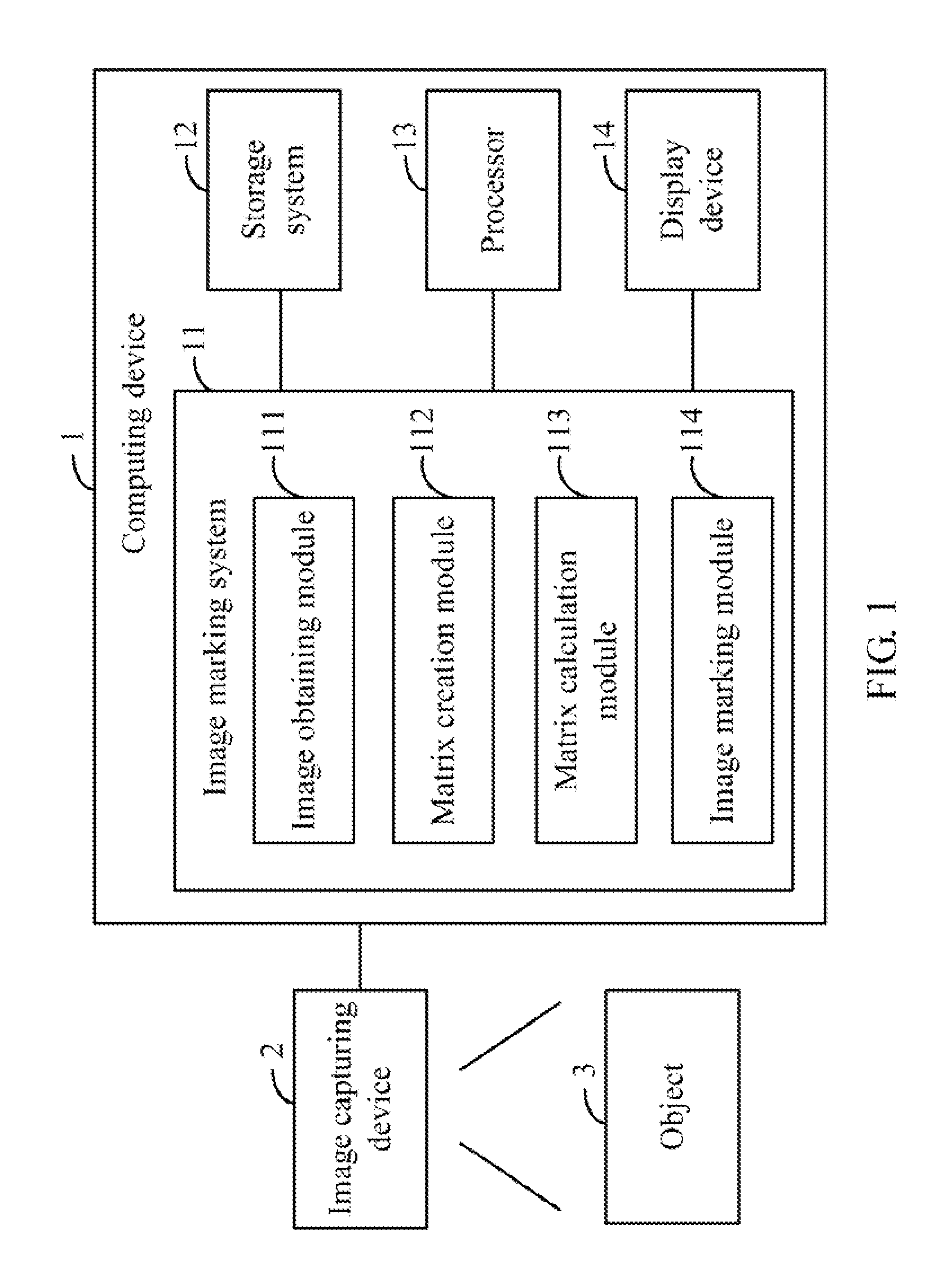
[0009]FIG. 1 is a block diagram of one embodiment of a computing device 1 including an image marking system 11. In the embodiment, the computing device 1 connects to an image capturing device 2 such as a digital camera. The image capturing device 2 is configured to capture a digital image (as shown in FIG. 3) of an object 3, such as a motherboard of a computer. The computing device 1 may further include a storage system 12, at least one processor 13, and a display device 14. The image marking system 11 can analyze the digital image and a standard image of the object 3 to find any parts of the two images which are not substantially identical (discrepant parts), and is able to mark out and disti...


PUM


Abstract

In a method for marking discrepancies of a captured image of an object, an image is captured and compared to a standard image. A discrepant image showing any discrepancies of the captured image is generated, and is separated into an R grayscale image, a G grayscale image, and a B grayscale image. An R channel matrix group, a G channel matrix group, and a B channel matrix group are created. R channel negative matrixes, G channel negative matrixes, and B channel negative matrixes are determined from the RGB channel matrix groups. RGB pixel groups are calculated based on the R channel negative matrixes, the G channel negative matrixes, and the B channel negative matrixes. A target pixel group to be marked is determined by calculating an intersection of the RGB pixel groups. The discrepancies of the digital image are marked out according to the target pixel group.

Description

BACKGROUND[0001]1. Technical Field[0002]Embodiments of the present disclosure relate to image processing technologies, and particularly to a system and method for marking discrepancies between two images.[0003]2. Description of Related Art[0004]Automatic optical inspection (AOI) devices are widely used to automatically inspect a captured image of an object which is being tested, such as a motherboard or a printed circuit board (PCB), to find discrepancies between the captured image and a standard image of the object. In general, an iteration method is usually used to inspect any discrepancies by analyzing each pixel of the two images, which is time consuming and costly.BRIEF DESCRIPTION OF THE DRAWINGS[0005]FIG. 1 is a block diagram of one embodiment of a computing device including an image marking system.[0006]FIG. 2 is a flowchart of one embodiment of a method for marking discrepancies of an image of an object using the system of FIG. 1.[0007]FIG. 3 is a schematic diagram illustra...

Claims


Application Information

Patent Timeline
IPC IPC(8): H04N5/225
CPCG06T2207/30141G06T7/001
Inventor WANG, GUANG-JIANZHANG, DAI-GANGZHAO, JIN-RONGLIU, XIAO-MEI
Owner WARECONN TECH SERVICE (TIANJIN) CO LTD
Why Eureka
Try Eureka