
Pixel adaptive intra smoothing

a smoothing and adaptive technology, applied in the field of spatial (intraimage) prediction of images, to achieve the effect of efficient intra prediction

Active Publication Date: 2012-06-07
SUN PATENT TRUST
View PDF13 Cites 102 Cited by
  • Summary
  • Abstract
  • Description
  • Claims
  • Application Information

AI Technical Summary

Benefits of technology

[0021]Given these problems with existing technology, it wo...

Problems solved by technology

Due to the block-wise coding, the superposed noise often has blocking characteristics, which result, in particular for strong quantization, in visible block boundaries in the decoded image.

Method used


Image

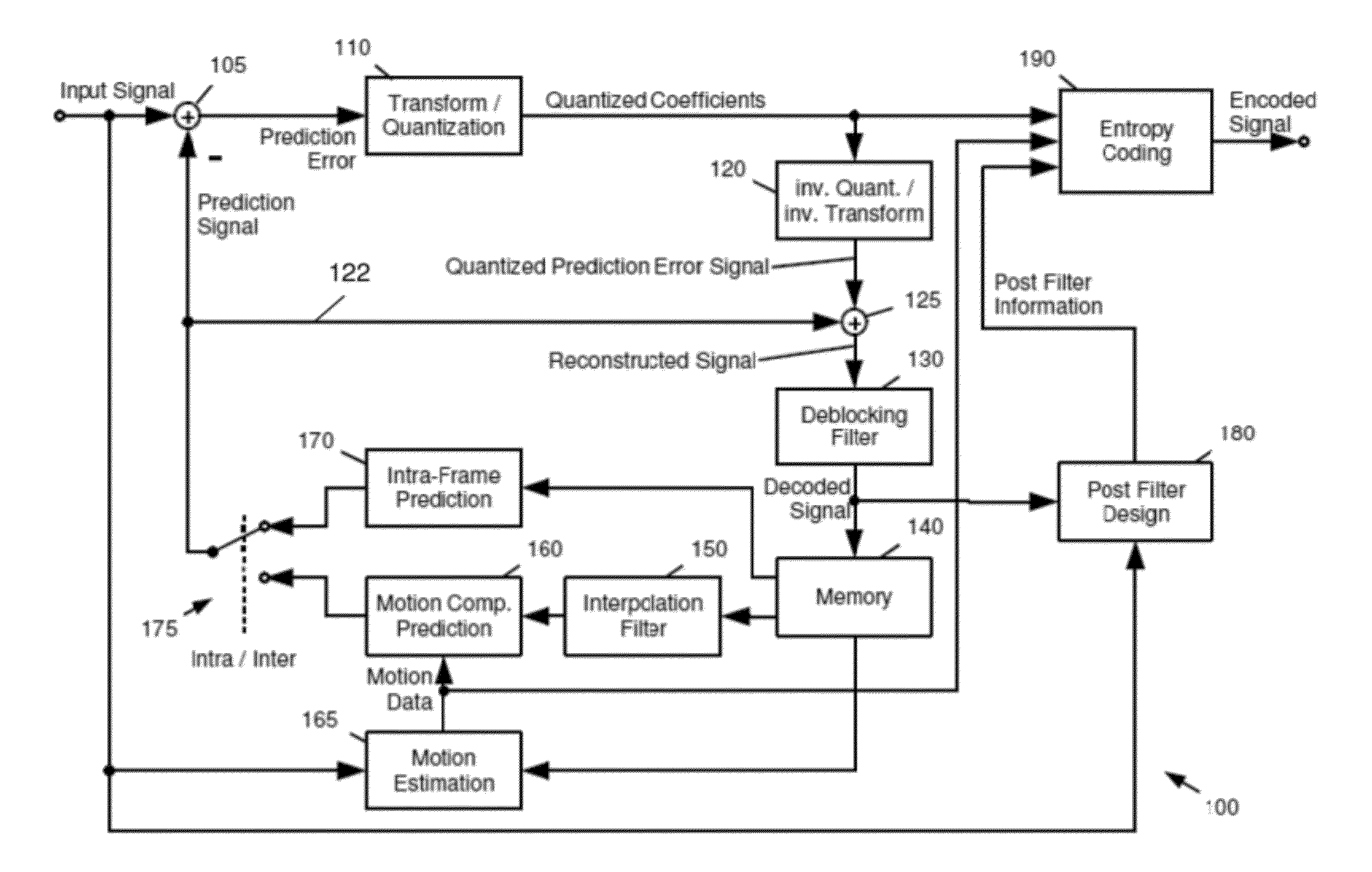
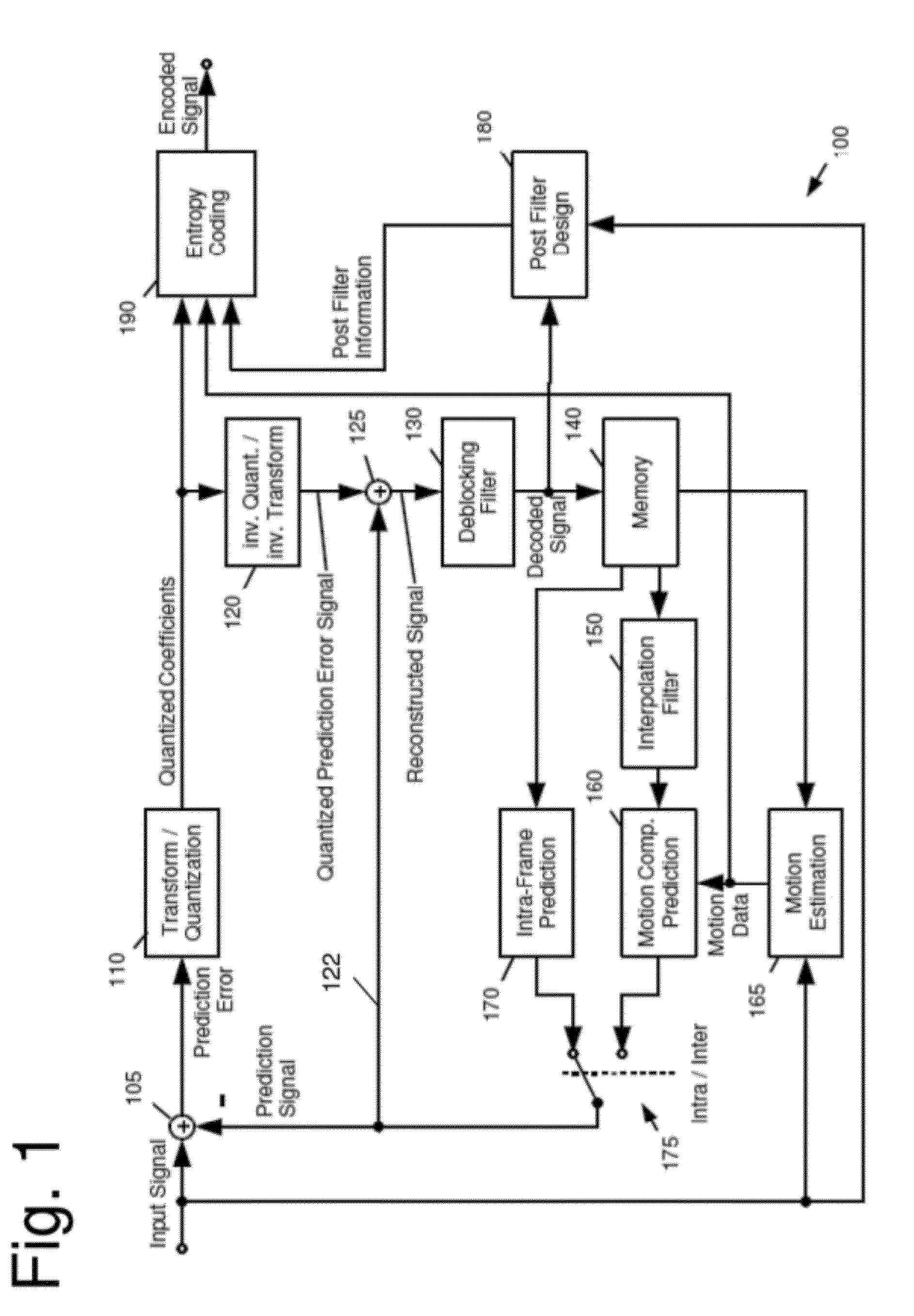
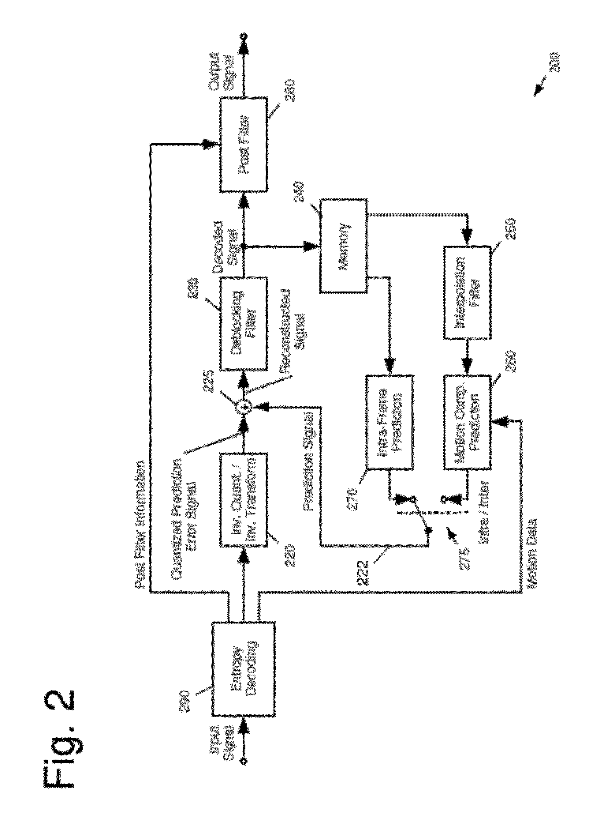
  • Pixel adaptive intra smoothing
  • Pixel adaptive intra smoothing
  • Pixel adaptive intra smoothing

Examples


Embodiment Construction

[0059]As can be seen from FIG. 4, the prediction error of intra prediction may include high frequency coefficients which are expensive to encode in terms of bitrate or distortion. This is, in particular, the case for any non-linear edges or edges which do not match one of the predefined prediction directions (such as the ones from FIG. 3B).

[0060]In order to remove high frequencies from the prediction signal of intra coding, it is advantageous to apply a low-pass filter on the reference pixels before performing intra prediction. FIG. 3A shows a block 300 of size (N+1)×(M+1) with pixels p(0, 0) to p(N, M), the top reference pixels p′(0, −1) to p′(N, −1) located on the top of the block 300, the top left reference pixel p′(−1, −1) and the left neighbouring reference pixels p′(−1, 0) to p′(−1, M). In addition, for the prediction, the available pixels to the right of the pixels 310 may be used, namely, pixels p′(N+1, −1) and p′(N+1+K, −1). The notation p with the apostrophe emphasizes tha...


PUM


Abstract

The present invention relates to spatial prediction of pixels of a block, the block being a block of a digital image. In particular, for a block pixel at least one reference pixel(s) is selected and out of the selected reference pixel(s), the block pixel is predicted. In particular, the prediction of the block pixel is performed depending on the distance of this pixel to the reference pixel(s) from which it is to be predicted.

Description

BACKGROUND OF THE INVENTION[0001]1. Field of the Invention[0002]The present invention relates to prediction of a block of an image. In particular, the present invention relates to spatial (intra-image) prediction of an image block.[0003]2. Description of the Related Art[0004]Spatial prediction has been employed in many applications. In particular, spatial prediction forms an essential part of many image and video coding and processing applications. In hybrid image or video coding algorithms, spatial prediction is typically employed for determining a prediction for an image block based on the pixels of already encoded / decoded blocks. On the other hand, spatial prediction may also be used as a part of post processing the decoded image or video signal, in particular for error concealment.[0005]The majority of standardized video coding algorithms are based on hybrid video coding. Hybrid video coding methods typically combine several different lossless and lossy compression schemes in or...

Claims


Application Information

Patent Timeline
IPC IPC(8): H04N7/32H04N19/593
CPCH04N19/105H04N19/46H04N19/593H04N19/82H04N19/117H04N19/182H04N19/11
Inventor DRUGEON, VIRGINIEWEDI, THOMASNARROSCHKE, MATTHIAS
Owner SUN PATENT TRUST
Learn More