Permeable Paving System

a paving system and permeable technology, applied in the field of paving systems, can solve the problems of insufficient realization of stormwater runoff needs to be managed, and the permeable paving system cannot be fully realized

Active Publication Date: 2012-06-07
PAVEDRAIN
View PDF14 Cites 11 Cited by
  • Summary
  • Abstract
  • Description
  • Claims
  • Application Information

AI Technical Summary

Benefits of technology

[0019]In another aspect of the invention, a first duct of the pair of ducts is proximate to a first side of the block, and a second duct of the pair of ducts is proximate to a second side of the block. Each cable is inserted alternately through a first duct and a second duct of successive blocks. In still another aspect of the invention, each block has a first end a second end opposite the first end. The first end of each block has a first non-planar geometric surface, and the second end of each block has a second non-planar geometric surface complementary to the first non-planar geometric surface such that the first end and the second end restrict lateral movement between adjacent blocks.

Problems solved by technology

Thus, it is a previously recognized problem with paving systems that stormwater runoff needs to be managed.
However, such a permeable pavement system has not been fully realized without incurring various disadvantages.
While these paver blocks, as disclosed, allow stormwater to drain down the sides of the block, they are still susceptible to one of the major drawbacks of existing permeable pavement systems: they are dependent on the aggregate interlock and aggregate subgrade and the underlying soil for infiltration.
Sandy or rocky soils have more cracks and fissures that allow the water to filter into and away from the surface, but heavy, clay soils do not drain quickly and require a longer retention time prior to the water entering the soil.
A disadvantage of this approach is the inability to clean out the underground storage systems once they are filled with sedimentation and particulates from stormwater runoff.

Method used


Image

  • Permeable Paving System
  • Permeable Paving System
  • Permeable Paving System

Examples


Embodiment Construction

[0054]Specific embodiments of the present invention will now be further described by the following, non-limiting examples which will serve to illustrate various features of significance. The examples are intended merely to facilitate an understanding of ways in which the present invention may be practiced and to further enable those of skill in the art to practice the present invention. Accordingly, the examples should not be construed as limiting the scope of the present invention.

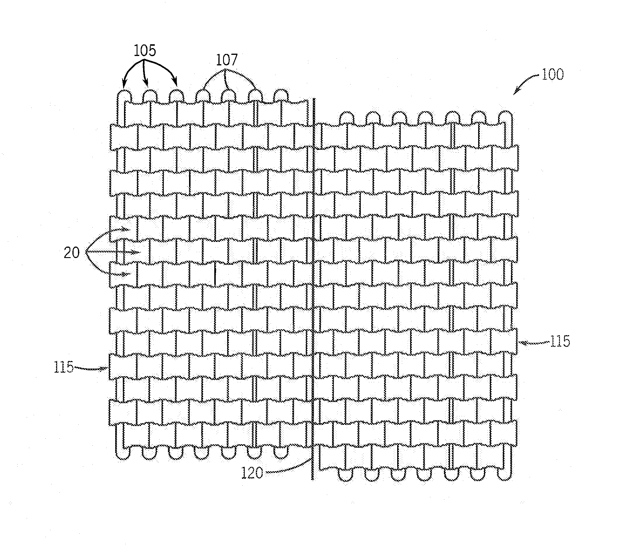
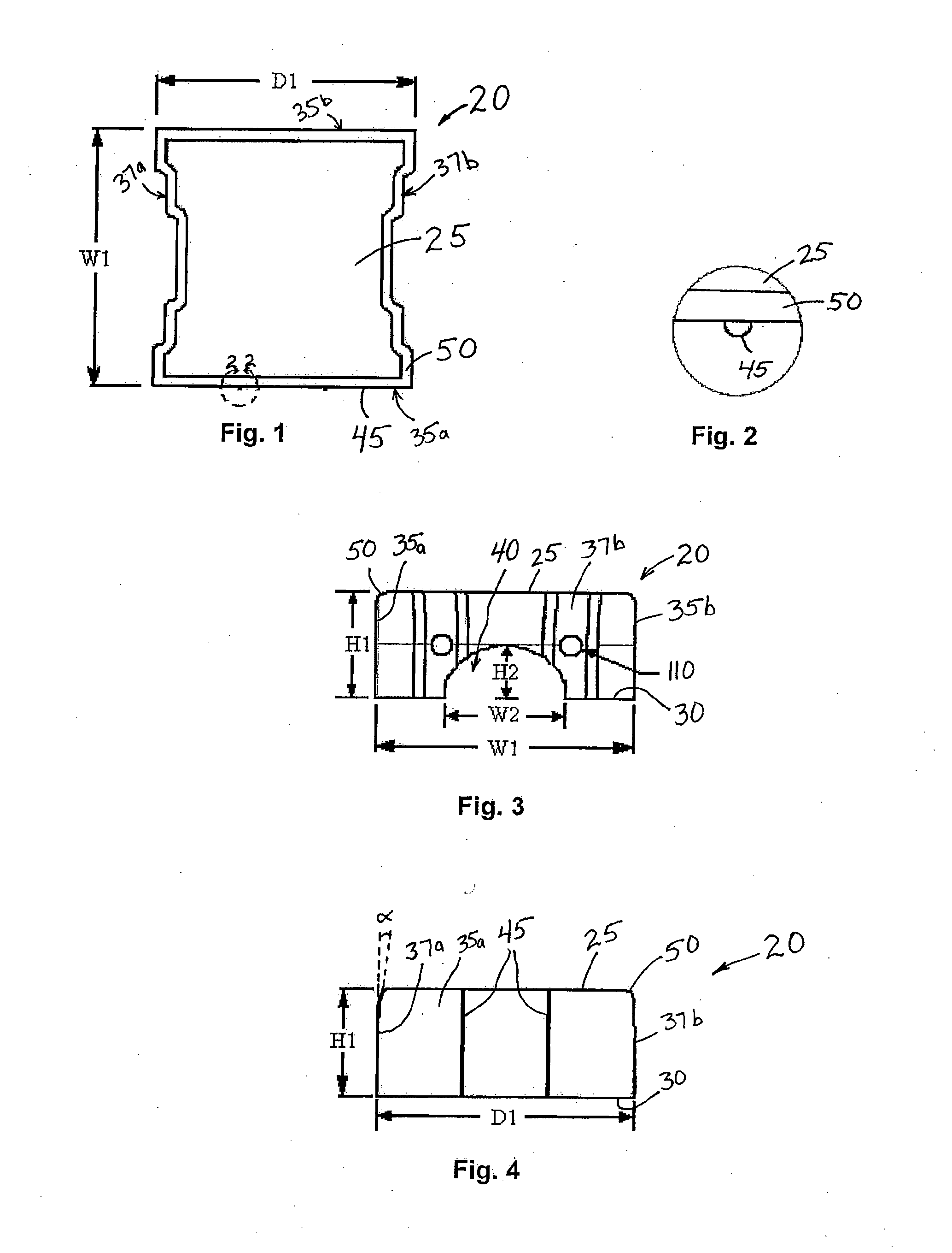
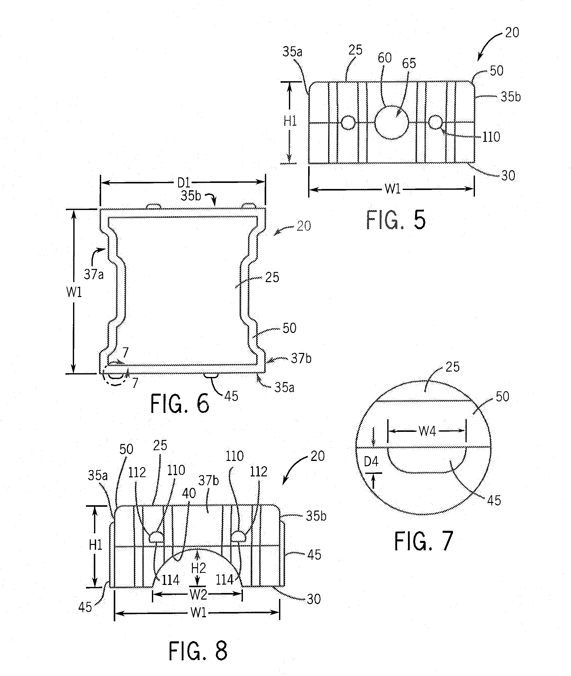
[0055]Turning initially to FIGS. 1-4, one embodiment of a block 20 used in a permeable pavement or permeable paving system 100 is illustrated. The block 20 is generally comprised of an upper surface 25, a lower surface 30, a first side wall, or side, 35a, a second side wall, or side, 35b, a first end 37a, a second end 37b, and a cavity 40. It is contemplated that the block 20, for example, a paver block, could be of any shape known to one of ordinary skill in the art, including, but not limited to, a squa...


PUM


Abstract

Systems and methods for a permeable pavement system are described. The permeable pavement system includes blocks designed to facilitate water seepage between the blocks and to permit water storage within the blocks. The blocks may be cabled together to create paving units that facilitate installation and maintenance of the pavement system. The permeable pavement system provides improved management of stormwater, reducing runoff and facilitating infiltration of stormwater into the subgrade below the paving system.

Description

CROSS-REFERENCE TO RELATED APPLICATIONS[0001]This application is a continuation-in-part of U.S. patent application Ser. No. 12 / 014,325, filed Jan. 15, 2008, the entire contents of which is incorporated herein by reference.BACKGROUND OF THE INVENTION[0002]1. Field of the Invention[0003]The present invention relates in general to the field of paving systems. More particularly, the present invention relates to a modular, permeable paving system. Specifically, a preferred embodiment of the present invention relates to a permeable paving system utilizing paving units made from blocks cabled together and providing fluid storage within the blocks.[0004]2. Discussion of the Related Art[0005]As is known to those skilled in the art, paving systems historically create a surface impervious to rain. The water that falls on the paved surface runs off the edge of the paving surface rather than being absorbed into the ground beneath the paved surface. It is recognized that an increasing number of p...

Claims


Application Information

Patent Timeline
Patent Type & Authority Applications(United States)
IPC IPC(8): E01C5/00
CPCE01C5/00E01C11/225E01C2201/207E01C2201/167E01C2201/202E01C2201/02Y02A10/30Y02A30/30
Inventor BUCH, DOUGLAS J.
Owner PAVEDRAIN
Why Eureka
Try Eureka