Spinal connecting members with tensioned cords and rigid sleeves for engaging compression inserts

a technology of connecting members and compression inserts, applied in the field of dynamic fixation assemblies, can solve the problems of facet joint compression during spinal movement, unresisted shear force, etc., and achieve the effect of variable segmental stiffness

Active Publication Date: 2012-06-07
JACKSON ROGER P
View PDF13 Cites 15 Cited by
  • Summary
  • Abstract
  • Description
  • Claims
  • Application Information

AI Technical Summary

Benefits of technology

[0007]Longitudinal connecting member assemblies according to the invention for use between at least two bone anchors provide dynamic, protected motion of the spine and may be extended to provide additional dynamic sections or more rigid support along an adjacent length of the spine, with fusion, if desired. A disclosed embodiment of a dynamic longitudinal connecting member assembly according to the invention has an inner segment or core made from a cord being tensioned and fixed at least at either end of the assembly. The cord is received by at least one hard, rigid, inelastic segment or sleeve, the sleeve attachable to at least one bone anchor. Illustrated sleeves of the invention include a surface or surfaces for direct engagement with a compression insert that in turn directly engages a shank of a polyaxial bone screw. Such a sleeve may also be configured for direct en

Problems solved by technology

Shear forces are not well resisted by the typical cord and spacer stabilization systems.
Such tensioned cord and spacer systems may also cause facet joint compression during spinal movement, especially flexion.
The complex dynamic conditions associated with spinal movement create challenges for the design of elongate elastic longitudinal connecting members that exhibit an adequate fatigue strength to provide stabilization and protected motio

Method used


Image

  • Spinal connecting members with tensioned cords and rigid sleeves for engaging compression inserts
  • Spinal connecting members with tensioned cords and rigid sleeves for engaging compression inserts
  • Spinal connecting members with tensioned cords and rigid sleeves for engaging compression inserts

Examples


Embodiment Construction

[0021]As required, detailed embodiments of the present invention are disclosed herein; however, it is to be understood that the disclosed embodiments are merely exemplary of the invention, which may be embodied in various forms. Therefore, specific structural and functional details disclosed herein are not to be interpreted as limiting, but merely as a basis for the claims and as a representative basis for teaching one skilled in the art to variously employ the present invention in virtually any appropriately detailed structure. It is also noted that any reference to the words top, bottom, up and down, and the like, in this application refers to the alignment shown in the various drawings, as well as the normal connotations applied to such devices, and is not intended to restrict positioning of the connecting member assemblies of the application and cooperating bone anchors in actual use.

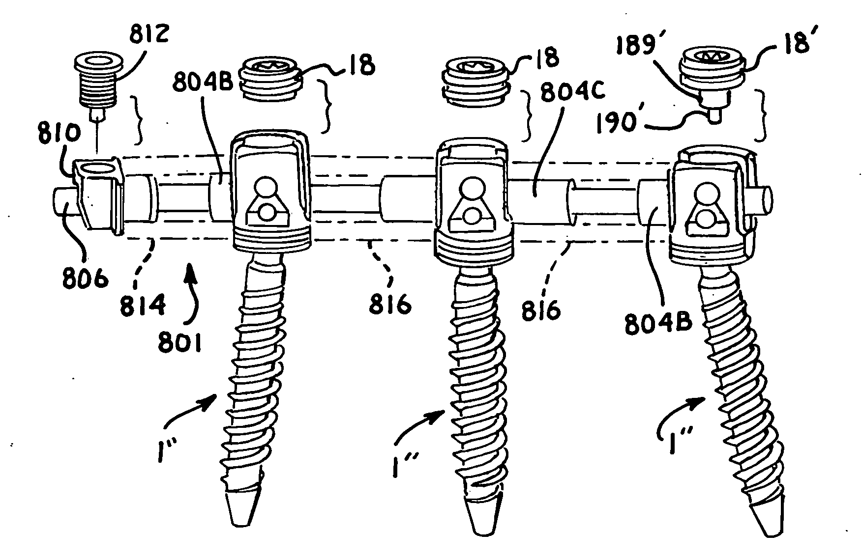
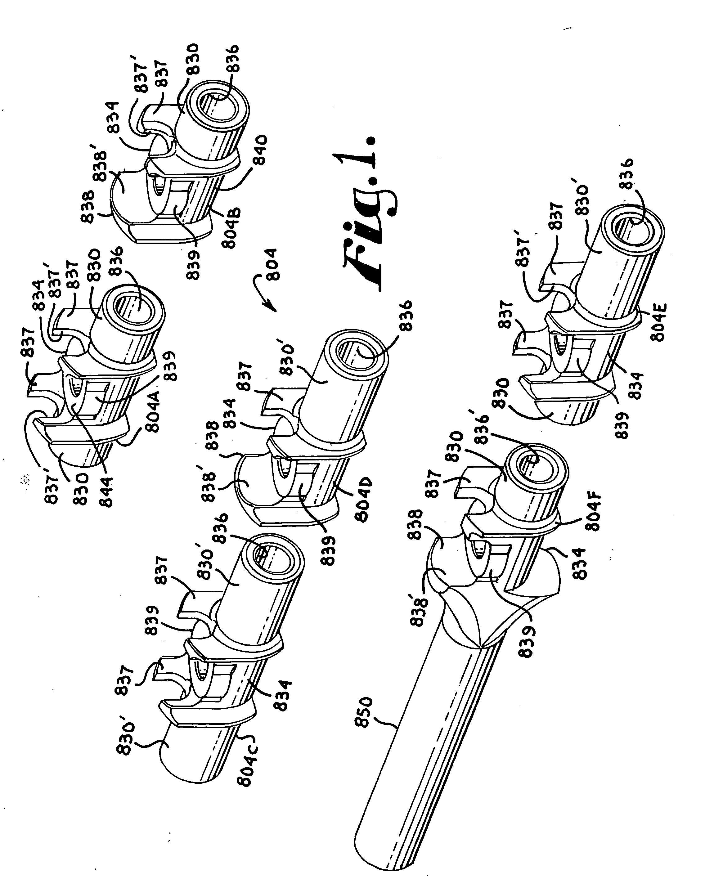
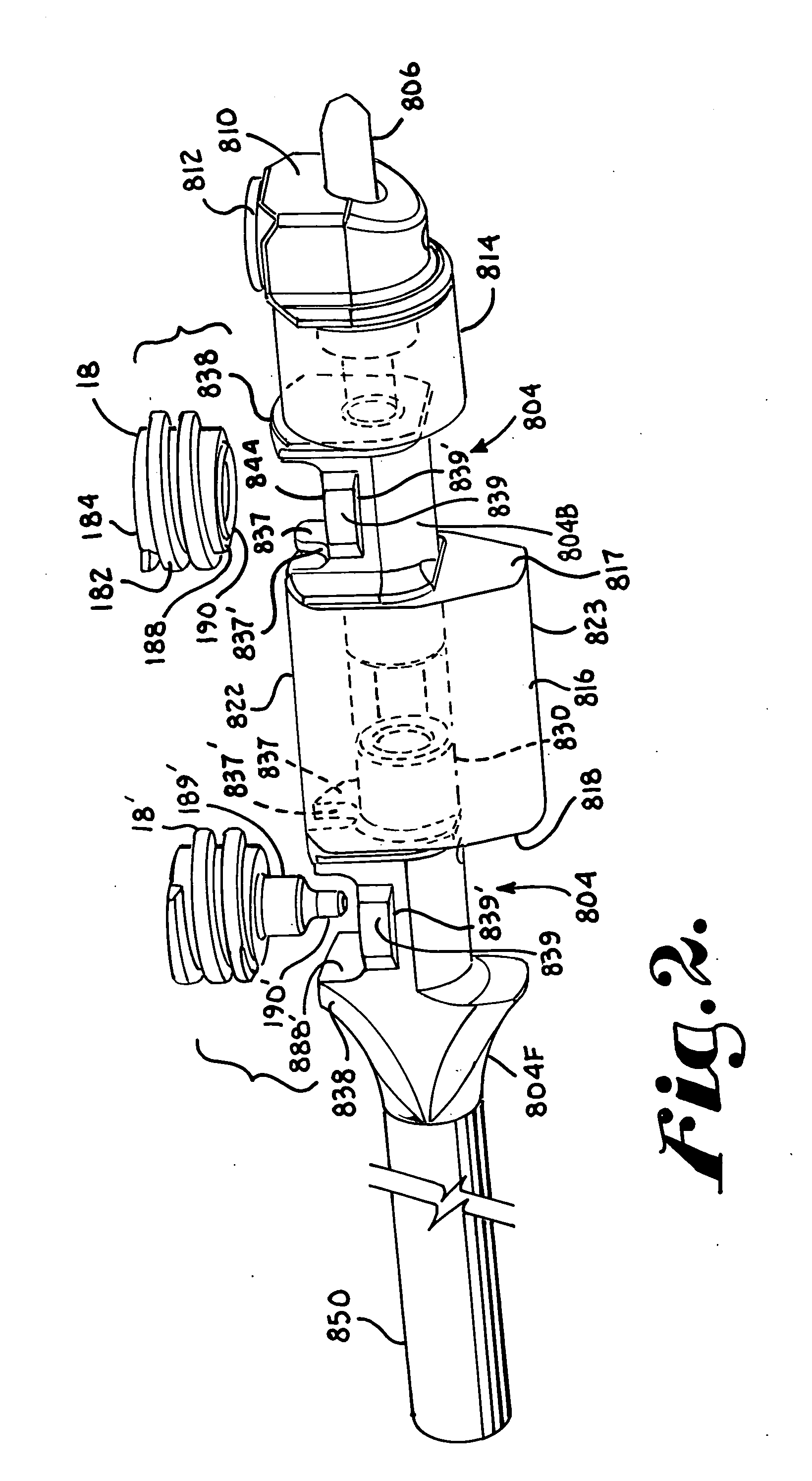
[0022]With particular reference to FIGS. 4-6 and 8, polyaxial bone screws, generally 1″ are show...


PUM


Abstract

A spinal implant having at least two bone anchors includes a longitudinal connecting member assembly having hard, non-elastic sleeves for attachment to the bone anchors, at least one spacer located between the bone anchors, and in some embodiments, an end elastic bumper and cord blocker. A cord is received within the rigid sleeves, the spacer and the bumper, the cord being in fixed or sliding relationship with cooperating sleeves. The sleeves include portions for direct engagement with bone screw inserts and closure tops and may include a channel for receiving a projected portion of a spacer.

Description

CROSS-REFERENCE TO RELATED APPLICATIONS[0001]This application claims the benefit of U.S. Provisional Patent Application Ser. No. 61 / 463,037 filed Feb. 11, 2011, incorporated by reference herein.[0002]This application is also a continuation-in-part of U.S. patent application Ser. No. 13 / 374,439 filed Dec. 29, 2011 that is incorporated by reference herein. This application is also a continuation-in-part of U.S. patent application Ser. No. 13 / 136,331 filed Jul. 28, 2011 that claims the benefit of U.S. Provisional Patent Application Ser. Nos. 61 / 400,504 filed Jul. 29, 2010, and 61 / 403,915 filed Sep. 23, 2010, all of which are incorporated by reference herein. This application is also a continuation-in-part of U.S. patent application Ser. No. 12 / 802,849 filed Jun. 15, 2010 that claims the benefit of the following U.S. Provisional Patent Application Ser. Nos. 61 / 268,708, filed Jun. 15, 2009; 61 / 270,754, filed Jul. 13, 2009; 61 / 336,911 filed Jan. 28, 2010; 61 / 395,564 filed May 14, 2010; 61...

Claims


Application Information

Patent Timeline
IPC IPC(8): A61B17/70
CPCA61B17/7004A61B17/7005A61B17/702A61B17/7035A61B17/7008
Inventor JACKSON, ROGER P.SURBER, JAMES L.
Owner JACKSON ROGER P
Why Eureka
Try Eureka