Generating and Detecting Acoustic Resonance in Thin Films

a thin film and acoustic resonance technology, applied in the direction of vibration measurement in solids, manufacturing tools, instruments, etc., can solve the problems of periodic expansion of thin films, deviation from actual thermal properties or given thicknesses, and periodic heating, etc., to achieve the effect of multiple measurement sites without undue cost or equipment siz

Inactive Publication Date: 2012-06-14
STEINKRAUS ROBERT +1
View PDF5 Cites 4 Cited by
  • Summary
  • Abstract
  • Description
  • Claims
  • Application Information

AI Technical Summary

Benefits of technology

[0013]In embodiments of this invention, the number of measurement sites may vary from 1 to more than 100; a system may be configured to measure all simultaneously, or sequentially or randomly, by employing by multiple fiber optic probes as disclosed in the instant invention. Conventional technologies use one probe and move the sample or the probe to measure multiple sites in a sample. The compact nature of the disclosed invention enables a multiplicity of measurement sites without undue cost or equipment size.

Problems solved by technology

Absorption of the periodic laser beam results in periodic heating and thus periodic expansion of the thin film.
Deviation from the actual thermal properties or the given thickness can arise from defects like voids, cracks, delamination, and the presence of foreign particles.
This technique requires continuous calibration, however, because in applications it cannot distinguish whether the signal is from changes in thickness or in the thermal properties.
In addition, it cannot measure the individual thicknesses in a film structure with two or more layers.
The prior art all measure the periodicity of thermal waves; all suffer the inability to measure two or more layers in physical contact.
The use of short laser pulses, however, requires a high peak power that can sometimes alter or melt the material, especially if the film is on top of a highly insulating film.
The signal is also highly dependent on the substrate; a layer thinner than 300 Å in thickness is difficult to measure with this technique.
This technique is accurate but slow and samples a large spot size.
Their use, however, are limited to semiconductors and insulators because the light has to penetrate through the film and changes in polarization and intensity are measured.
Light with wavelengths in the visible region does not penetrate metals, so ellipsometry cannot be used to measure metal films.
Other systems for measuring the thickness of metal, semiconductor and insulator films are destructive techniques, that is, the measurement requires mechanical contact with the film which is undesirable.

Method used


Image

  • Generating and Detecting Acoustic Resonance in Thin Films
  • Generating and Detecting Acoustic Resonance in Thin Films
  • Generating and Detecting Acoustic Resonance in Thin Films

Examples


Embodiment Construction

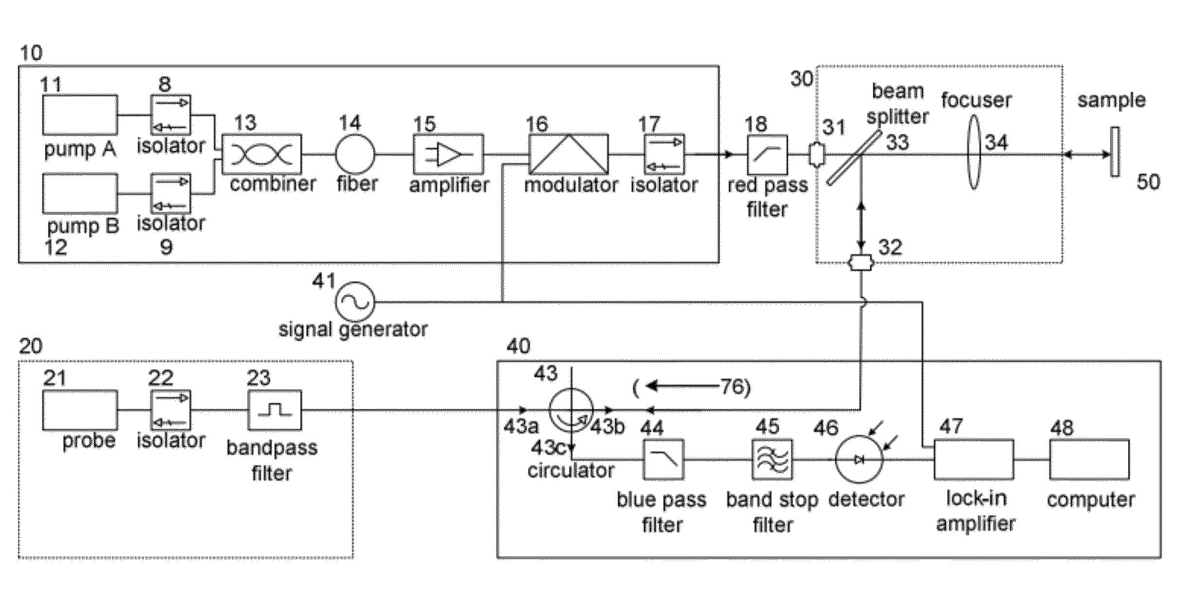
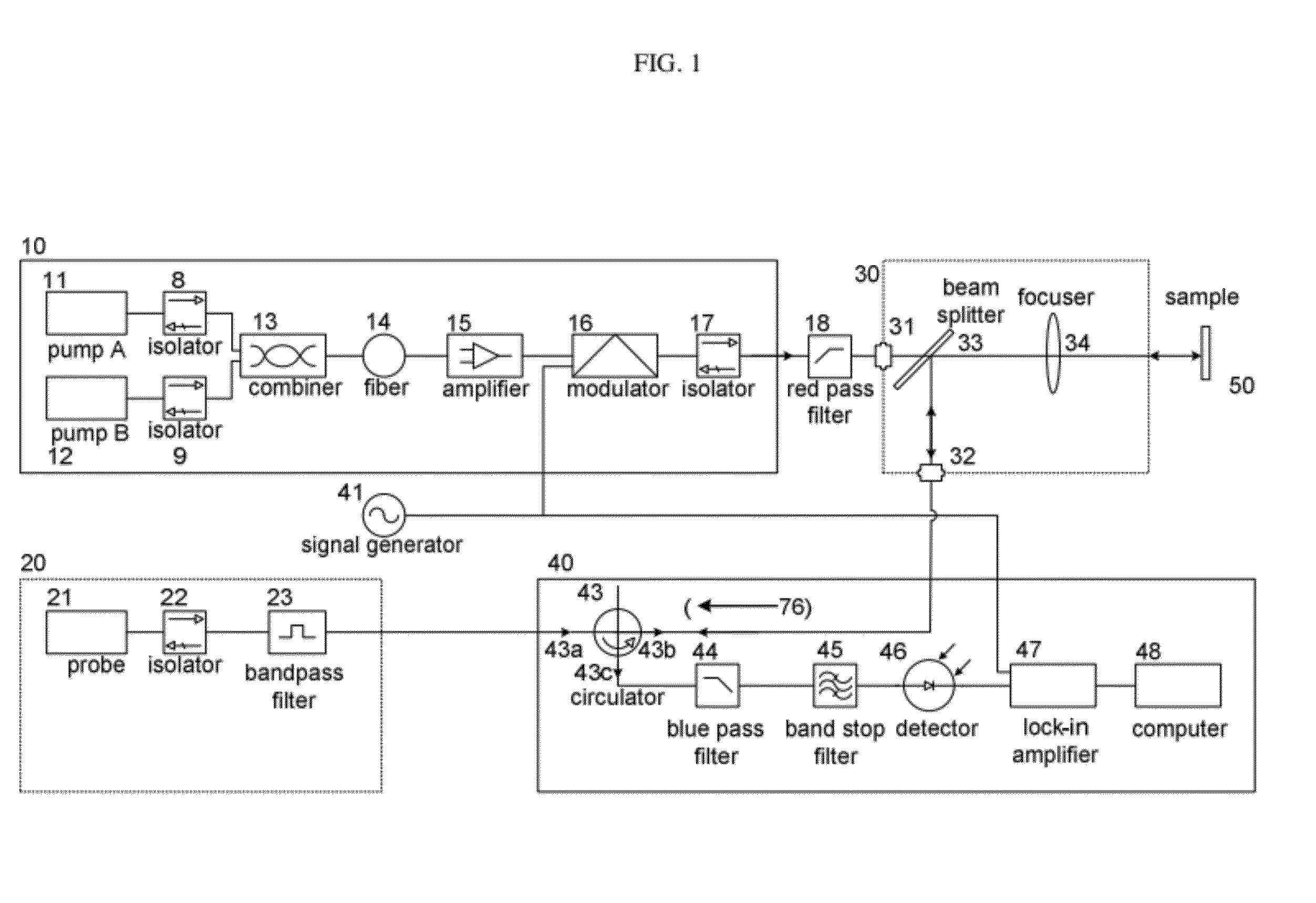
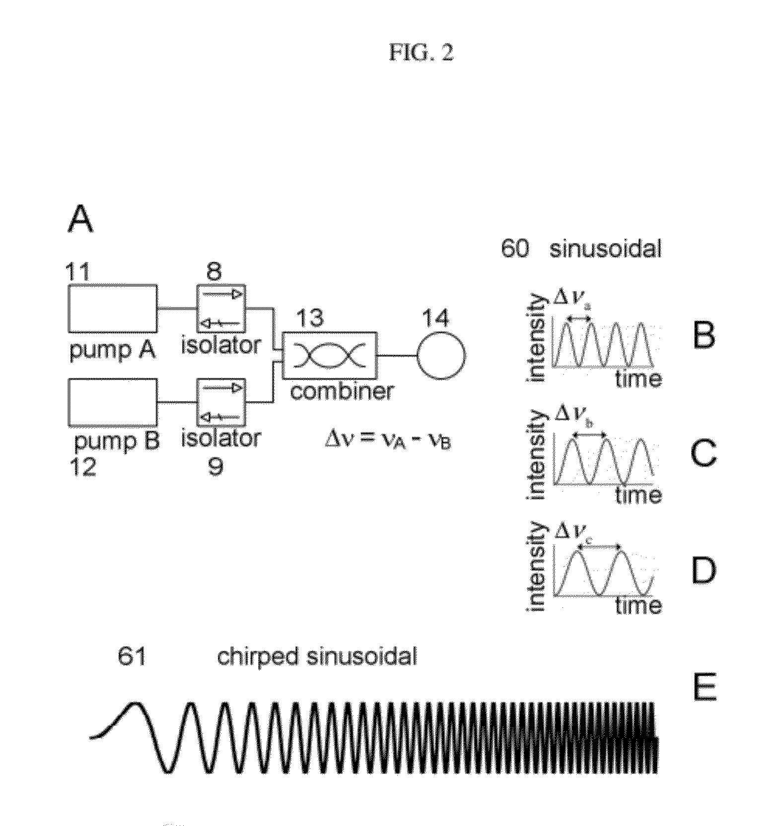
[0022]FIG. 1 is a schematic diagram of one embodiment of the apparatus of this invention. The major subsystems include the pump beam system 10, the probe system 20, the focusing optic 30, and the detection system 40. The components enclosed in 10 define the system for the pump beam, which comprises a means for generating an acoustic wave, optionally resonant, in a sample 50 comprising first and second pump beams heterodyned, optionally, in a first optical fiber 14, to produce a periodic waveform with a frequency component between about 10 MHz to about 10 THz. A means for generating an acoustic wave, optionally resonant, comprises 11 and 12, two lasers; in one embodiment the lasers are DFB, distributive fiber grating, cw, continuous wave, lasers of about constant intensity and of different wavelengths; the wavelengths are in a range of about 10 nanometers to about 100 microns. Optionally, a laser wavelength is tuned by a temperature controller and the output light coupled into an opt...


PUM

PropertyMeasurementUnit
thicknessesaaaaaaaaaa
wavelengthsaaaaaaaaaa
areaaaaaaaaaaa

Abstract

A method and apparatus for film thickness measurements by inducing and detecting acoustic resonance in a sample is disclosed. Acoustic resonance is induced by generating acoustic waves using heterodyned laser beams to frequency-tune a periodic waveform; the detection is done by monitoring changes in a continuous wave, constant intensity laser probe beam. The laser beams and optical system are fiber-optic based.

Description

CROSS-REFERENCE TO RELATED APPLICATIONS[0001]All references in the accompanying Information Disclosure Statement are incorporated herein in their entirety by reference.FIELD OF THE INVENTION[0002]This invention relates to an apparatus for measuring the properties of thin films. More specifically to a system that generates a periodic waveform incident on a thin film, and detecting a reflected signal that is different when the period of the generated waveform corresponds to the acoustic resonance of the film.BACKGROUND OF THE INVENTION[0003]A fast, non-destructive method of measuring thin film properties is of interest in the manufacturing process of electronic, optical, and mechanical devices that employ thin films. In one technique using thermal waves and described in several patents, for example U.S. Pat. No. 4,522,510, U.S. Pat. No. 4,513,385, U.S. Pat. No. 4,679,946 and prior art, for example, A. Rosencwaig et. al.; Applied Physics Letters 43 (2), 166, 1983; A. Rosencwaig et al.;...

Claims


Application Information

Patent Timeline
Patent Type & Authority Applications(United States)
IPC IPC(8): G01N29/04G01N29/00
CPCG01N29/12Y10T29/49764G01N2291/0237G01N29/2418
Inventor STEINKRAUS, ROBERTBELLO, ABNER F.
Owner STEINKRAUS ROBERT
Why Eureka
Try Eureka