Merged ramp/oscillator for precise ramp control in one cycle pfc converter

a converter and ramp technology, applied in the direction of electric variable regulation, process and machine control, instruments, etc., can solve the problems of significant power factor loss, significant ramp errors, etc., and achieve accurate power factor correction without cost

Active Publication Date: 2009-11-05
INFINEON TECH AMERICAS CORP
View PDF3 Cites 32 Cited by
  • Summary
  • Abstract
  • Description
  • Claims
  • Application Information

AI Technical Summary

Benefits of technology

[0012]The present invention provides a simplified solution to the problems of the prior art circuits. The present invention provides accurate power factor correction without dithering induced by calibration and without the cost associated with the ramp generator and calibrator of the prior art solution.

Problems solved by technology

Any error in this voltage results in significant loss of power factor.
Unavoidable mismatches between clock and ramp voltage result in significant loss of power factor.
Unavoidable mismatches between clock and ramp components as well as offset terms within amplifiers when utilizing this traditional method lead to significant errors in the ramp.
However, it cannot provide sufficient mitigation over the full operating range of the circuit, and is useless if the frequency is user-programmable.
Offset errors and propagation delay issues in the calibration circuit can lead to errors in the ramp.
However, these errors are small enough so that this technique provides accurate PFC.
Drawbacks to this technique are first, dithering in the calibration circuit leads to dithering in the duty cycle that many systems cannot tolerate and secondly, the circuit is more complex so the silicon required to build the ramp and calibrator can be significant.

Method used


Image

  • Merged ramp/oscillator for precise ramp control in one cycle pfc converter
  • Merged ramp/oscillator for precise ramp control in one cycle pfc converter
  • Merged ramp/oscillator for precise ramp control in one cycle pfc converter

Examples


Embodiment Construction

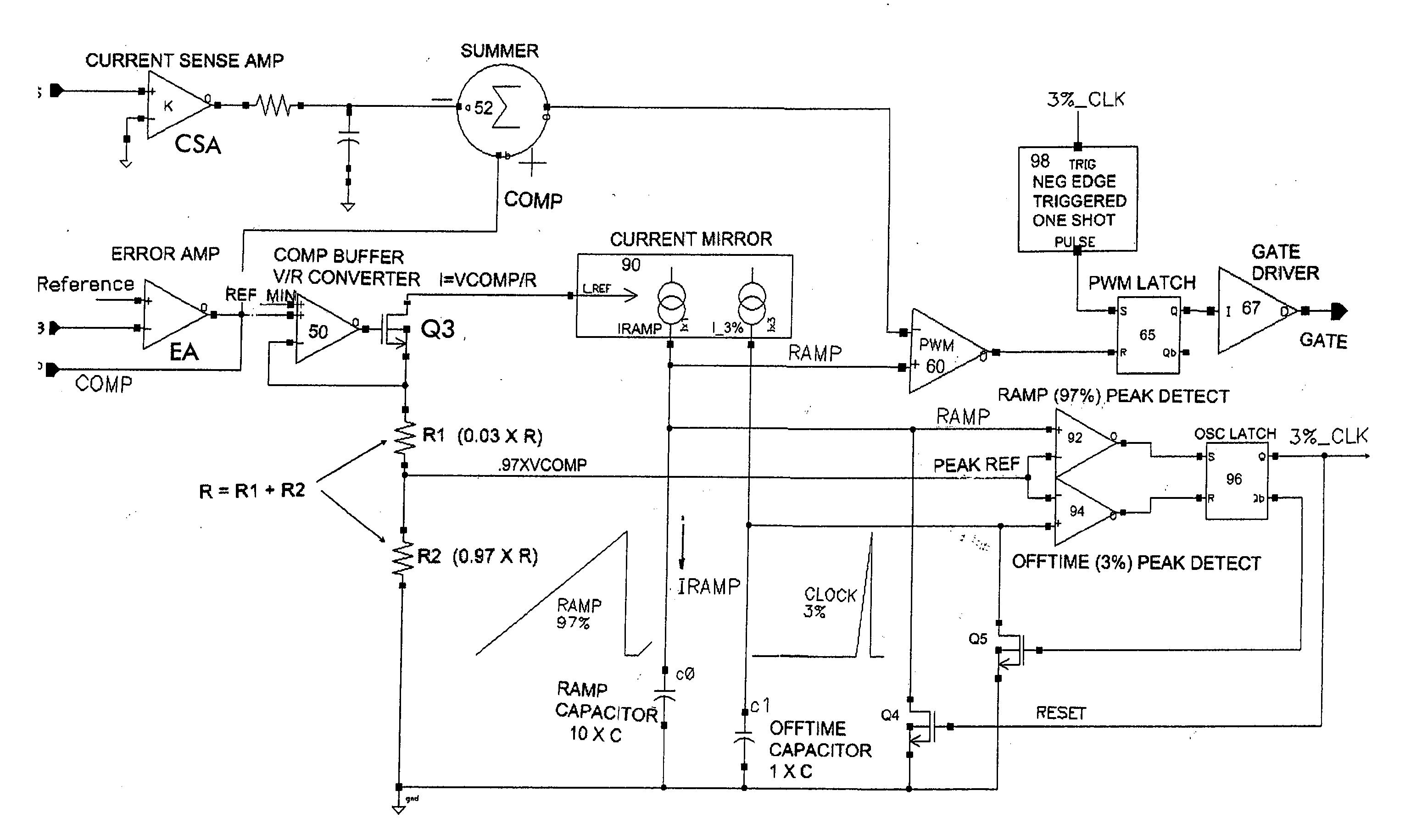
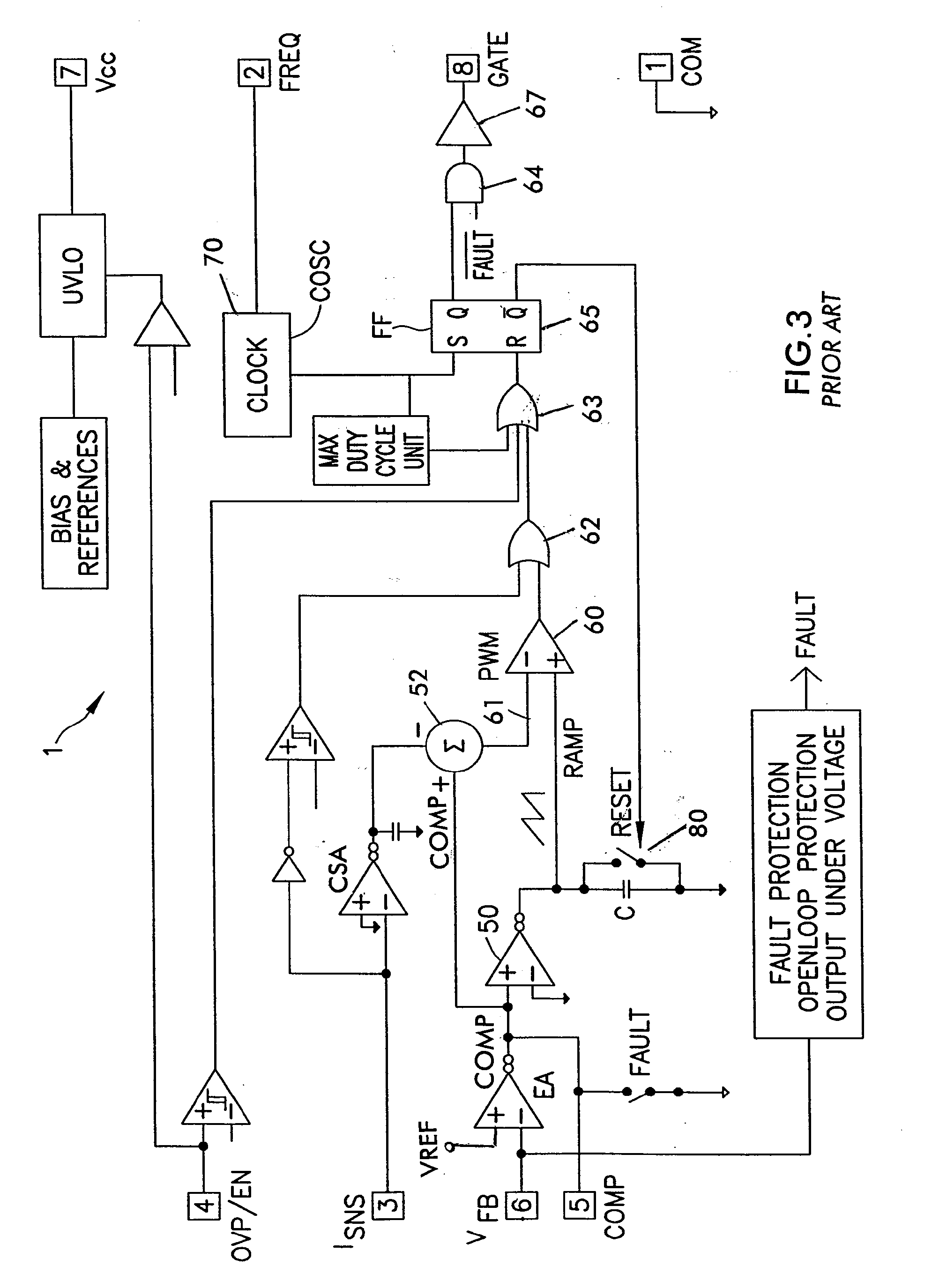
[0026]With reference to FIG. 4, a one cycle control circuit employing the combined ramp generator and oscillator of the invention is shown.

[0027]The error amplifier EA is the same as in the prior art circuit of FIG. 3. The error amplifier output COMP is provided to the amplifier 50 as in the prior art circuit. The output of the amplifier 50 sets a current in a resistor R(R1+R2) through a switch Q3. The resistor R may be variable to determine the reference current. The current in the resistor R is provided though a current mirror 90, in the illustrated embodiment, a one-to-one current mirror. The current mirror sets up a charging ramp current in the capacitor CØ. The current is designated IRAMP. This establishes a ramp current through the capacitor CØ. The ramp voltage waveform RAMP is provided to the PWM comparator 60. The error signal COMP (as adjusted by the sensed output current in summing stage 52) is compared to the RAMP. When the RAMP exceeds the adjusted error signal, the PWM...


PUM


Abstract

A one cycle power factor correction converter circuit comprising a switch for controlling a DC output voltage of the converter circuit, the switch being switched by a drive signal having a frequency determined by a clock signal; the converter circuit being provided with a DC input voltage and producing the DC output voltage, the DC input voltage being rectified from an AC input; a controller circuit for controlling an on-time or off-time of the switch to set the output voltage and to achieve power factor correction at the AC input; the controller circuit comprising an error amplifier receiving a feedback voltage from the output of the converter circuit and a reference voltage and producing an error signal; a ramp generator receiving the error signal and generating a first ramp signal by integrating a signal related to the error signal; a pulse width modulation circuit receiving the first ramp signal and a signal related to the error signal and producing a pulse width modulated signal by comparing the first ramp signal and the signal related to the error signal; the pulse width modulated signal determining the on-time or off-time of the switch to control the output voltage with power factor correction; further comprising a circuit for terminating the first ramp signal when a predetermined inequality exists between the first ramp signal and a reference signal and for developing the clock signal from the first ramp signal.

Description

CROSS-REFERENCE TO RELATED APPLICATIONS[0001]The present application is related to U.S. application No. 11 / 207,509, filed Aug. 19, 2005, entitled METHOD AND APPARATUS FOR CALIBRATING A RAMP SIGNAL, U.S. Publication No. 2006 / 0043956, the entire disclosure of which is incorporated by reference herein.BACKGROUND OF THE INVENTION[0002]The present invention relates to one cycle (also known as single cycle) power factor correction (PFC) converters, and in particular, to a simplified circuit for establishing the ramp signal and clock signal in such converter circuits. In particular, the present invention provides a method and circuit for generating a combined ramp and oscillator signal for such converter circuits.[0003]A critical requirement to achieve near unity power factor, when utilizing the single cycle control architecture, is to establish a pulse width modulation (PWM) ramp reference that integrates the error signal over the switching period (T) of the controller. In this architectu...

Claims


Application Information

Patent Timeline
Patent Type & Authority Applications(United States)
IPC IPC(8): G05F1/70
CPCG05F1/70Y02B70/126H02M1/4225Y02B70/10
Inventor SISSON, PAUL
Owner INFINEON TECH AMERICAS CORP
Why Eureka
Try Eureka