
Illumination optical system and 3D image acquisition apparatus including the same

an optical system and optical system technology, applied in the field of illumination optical systems and three-dimensional (3d) image acquisition apparatuses, can solve the problems of not being used for extracting depth information, difficult to obtain precise depth information with these methods, and loss of considerable illumination light, so as to achieve the effect of inhibiting speckle nois

Active Publication Date: 2012-06-14
SAMSUNG ELECTRONICS CO LTD
View PDF6 Cites 32 Cited by
  • Summary
  • Abstract
  • Description
  • Claims
  • Application Information

AI Technical Summary

Benefits of technology

[0010]One or more exemplary embodiments provide an illumination system which is capable of obtaining more precise depth information in a 3-dimensional (3D) image acquisition apparatus.
[0011]One or more exemplary embodiments provide an illumination optical system able to efficiently inhibit speckle noise.

Problems solved by technology

However, according to these methods, the greater the camera-to-object distance, the more imprecise the obtained depth information becomes, and these methods are highly dependent on the surface states of the objects being imaged.
Thus, acquiring precise depth information with these methods is difficult.
However, in general, the field of view in a 3D camera does not match the field of illumination of its illumination optical system, and thus a considerable amount of illumination light may be lost and not used for extracting depth information.
However, when a coherent light source is used to emit light onto an object, speckle noise from the coherent light source may deteriorate the quality of the obtained image.
However, due to light scattering or absorption by the diffuser, depth information may be less precisely obtained.

Method used


Image

  • Illumination optical system and 3D image acquisition apparatus including the same
  • Illumination optical system and 3D image acquisition apparatus including the same
  • Illumination optical system and 3D image acquisition apparatus including the same

Examples


Embodiment Construction

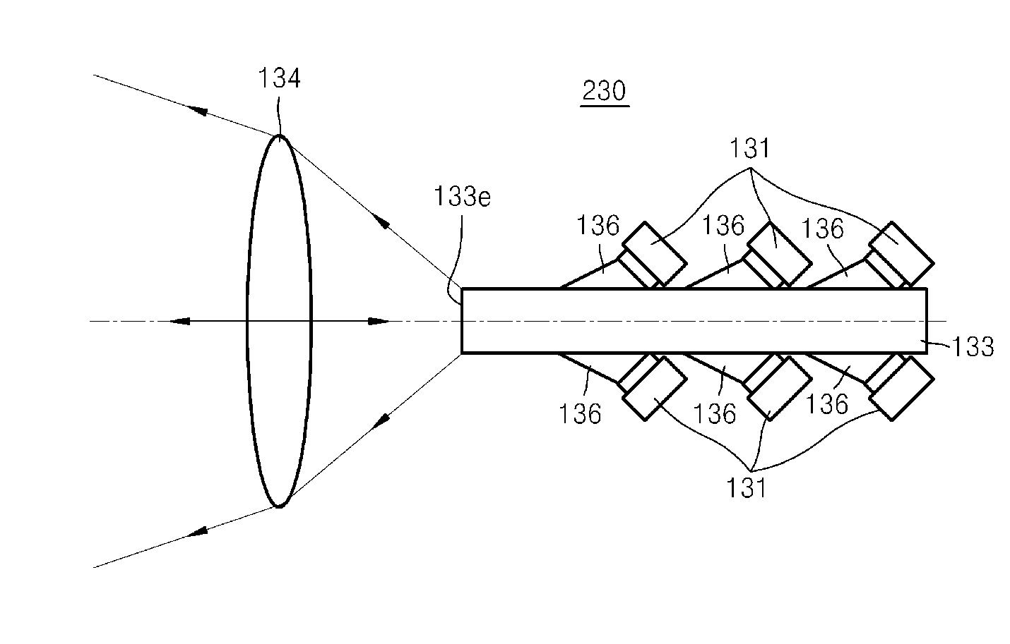
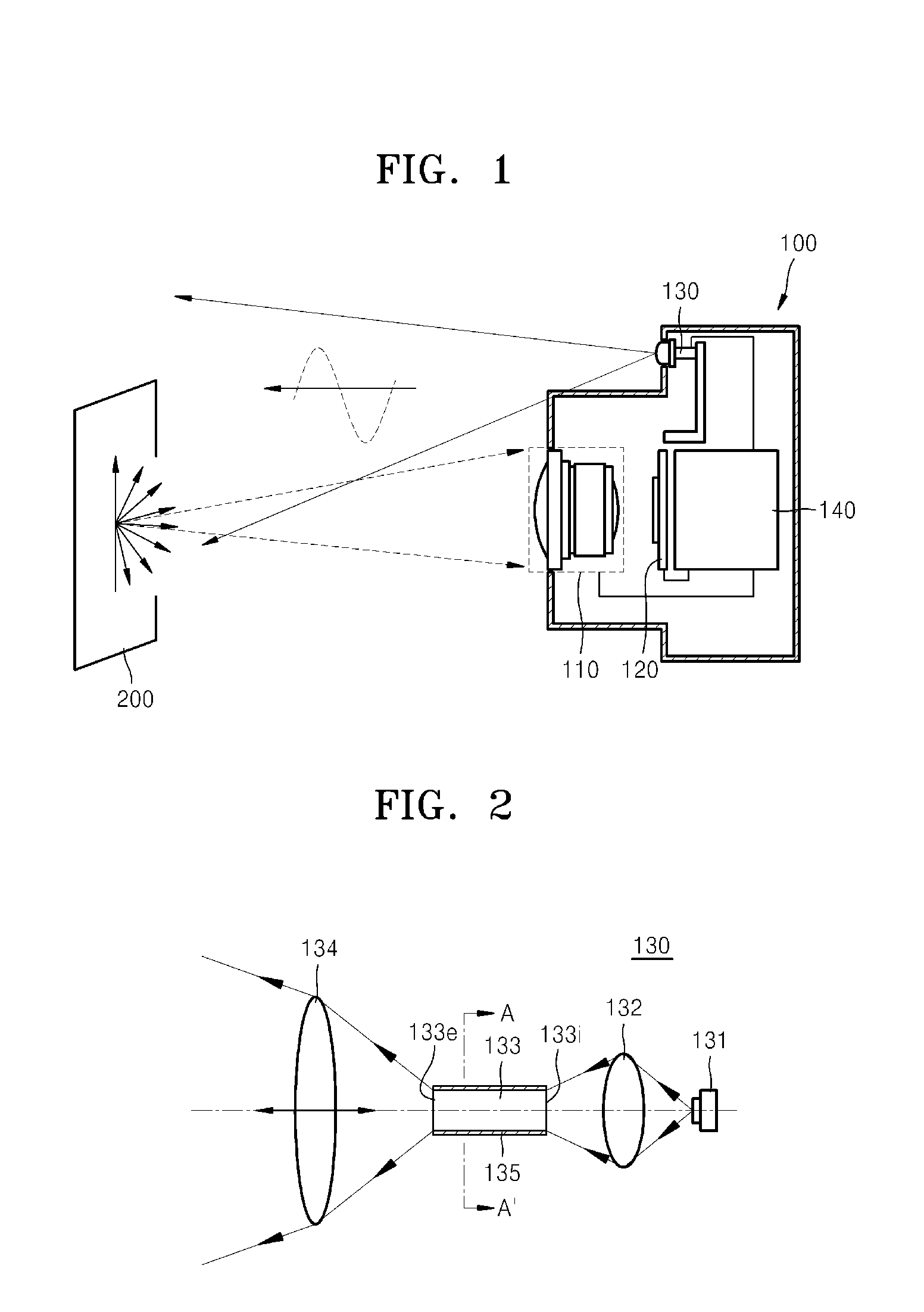
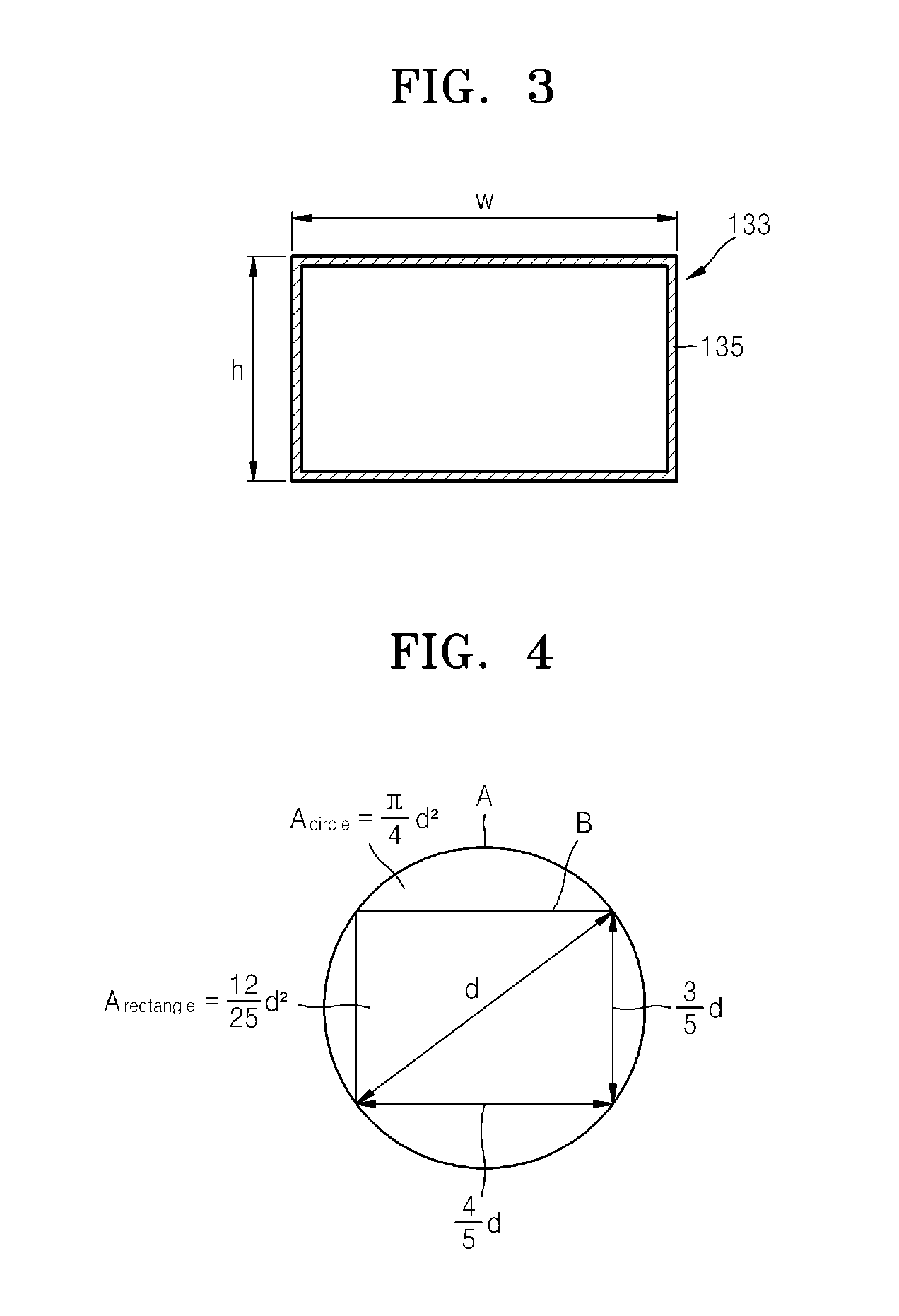
[0043]Reference will now be made in detail to exemplary embodiments of an illumination system and a 3D image acquisition apparatus including the same, examples of which are illustrated in the accompanying drawings. In the drawings, like reference numerals in the drawings denote like elements, and the size of each component may be exaggerated for clarity.

[0044]FIG. 1 is a conceptual view illustrating a structure of a 3D image acquisition apparatus 100, according to an exemplary embodiment. Referring to FIG. 1, the 3D image acquisition apparatus 100 may include an objective lens 110 for focusing an image of an object 200, an image processing unit 120 for processing the image focused by the objective lens 110 to generate an image signal, an illumination optical system 130 for illuminating the object 200 to acquire depth information about the object 200, and a control unit 140 for controlling the operations of the objective lens 110, the image processing unit 120, and the illumination o...


PUM


Abstract

An illumination optical system of a 3-dimensional (3D) image acquisition apparatus and a 3D image acquisition apparatus including the illumination optical system. The illumination optical system of a 3D image acquisition apparatus includes a beam shaping element which outputs light having a predetermined cross-sectional shape which is proportional to a field of view of the 3D image acquisition apparatus. The beam shaping element may adjust a shape of illumination light according to its cross-sectional shape. The beam shaping element may uniformly homogenize the illumination light without causing light scattering or absorption.

Description

CROSS-REFERENCE TO RELATED APPLICATION[0001]This application claims priority from Korean Patent Application No. 10-2010-0127866, filed on Dec. 14, 2010, in the Korean Intellectual Property Office, the disclosure of which is incorporated herein by reference.BACKGROUND[0002]1. Field[0003]Apparatuses consistent with exemplary embodiments relate to illumination optical systems and three-dimensional (3D) image acquisition apparatuses including the same, and more particularly, to an optical system in which a field of illumination coincides with a field of view in order to obtain more precise depth information, and a 3D image acquisition apparatus including the optical system.[0004]2. Description of the Related Art[0005]Recent advances in 3D display apparatuses and an increasing demand therefore highlight the significance of 3D content in which depth can be perceived. Accordingly, research is increasing into 3D image acquisition apparatuses such as 3D cameras that enable users to create 3D...

Claims


Application Information

Patent Timeline
IPC IPC(8): H04N13/02G03B15/06G03B15/02G01S17/894
CPCH04N13/0253G01S7/4814G01S17/89H04N13/254G01S17/894H04N23/56H04N13/20H04N13/271G02B27/10G03B15/03
Inventor PARK, YONG-HWASHIRANKOV, ALEXANDERYOU, JANG-WOOROZHKOV, O
Owner SAMSUNG ELECTRONICS CO LTD
Learn More