Light guide module, backlight module and fabrication method of light guide module

a technology of backlight module and light guide module, which is applied in the direction of lighting and heating apparatus, instruments, paper/cardboard containers, etc., can solve the problems of ineffective reduction of patterned adhesive layer, inability to effectively reduce the doped diffusive particle, and inability to enhance the optical performance of the backlight source provided by the backlight modul

Inactive Publication Date: 2012-06-14
YOUNG LIGHTING TECHNOLOGY INC
View PDF6 Cites 45 Cited by
  • Summary
  • Abstract
  • Description
  • Claims
  • Application Information

AI Technical Summary

Benefits of technology

[0017]According to an exemplary embodiment of the disclosure, a density of the light-transmissive adhesive gels increases as a distance of the light-transmissive adhesive gels from the light incidence surface increases.
[0018]According to an exemplary embodiment of the disclosure, a size of the light-transmissive adhesive gels increases as a distance of the light-transmissive adhesive gels from the light incidence surface increases.
[0024]Accordingly, the embodiment or the embodiments of the invention may have at least one of the advantages, the adhesive pattern layer constructed with the plurality of the light-transmissive adhesive gels is applied to secure the diffuse reflector to the bottom surface of the light guide plate, wherein the light-transmissive adhesive gels do not contain any diffusive particles. Hence, the formation of the adhesive pattern layer is not limited by the size of the diffusive particles, and the adhesive pattern layer with a smaller dimension and a more even distribution of the light-transmissive adhesive gels is formed. Hence, the light field distribution of the light beam emitted from the light exiting surface of the light guide plate may have better light uniformity. In other words, the backlight module provides a backlight source with better light uniformity. Moreover, the backlight module applies a light-transmissive adhesive gels having adhesive property to bond the light guide plate and the diffuse reflector together. Accordingly, a backlight source with better light uniformity is provided. Moreover, a fabrication method of a light guide module for forming a light guide module with at least one of the above-mentioned merits is provided.

Problems solved by technology

Hence, limited by the traditional screen printing process, the dimensions of the patterned adhesive layer 78 and the diffusive pattern layer 71 doped with the diffusive particles may not be effectively reduced and the optical performance of the backlight source provided by the backlight module may not be enhanced.

Method used


Image

  • Light guide module, backlight module and fabrication method of light guide module
  • Light guide module, backlight module and fabrication method of light guide module
  • Light guide module, backlight module and fabrication method of light guide module

Examples


Embodiment Construction

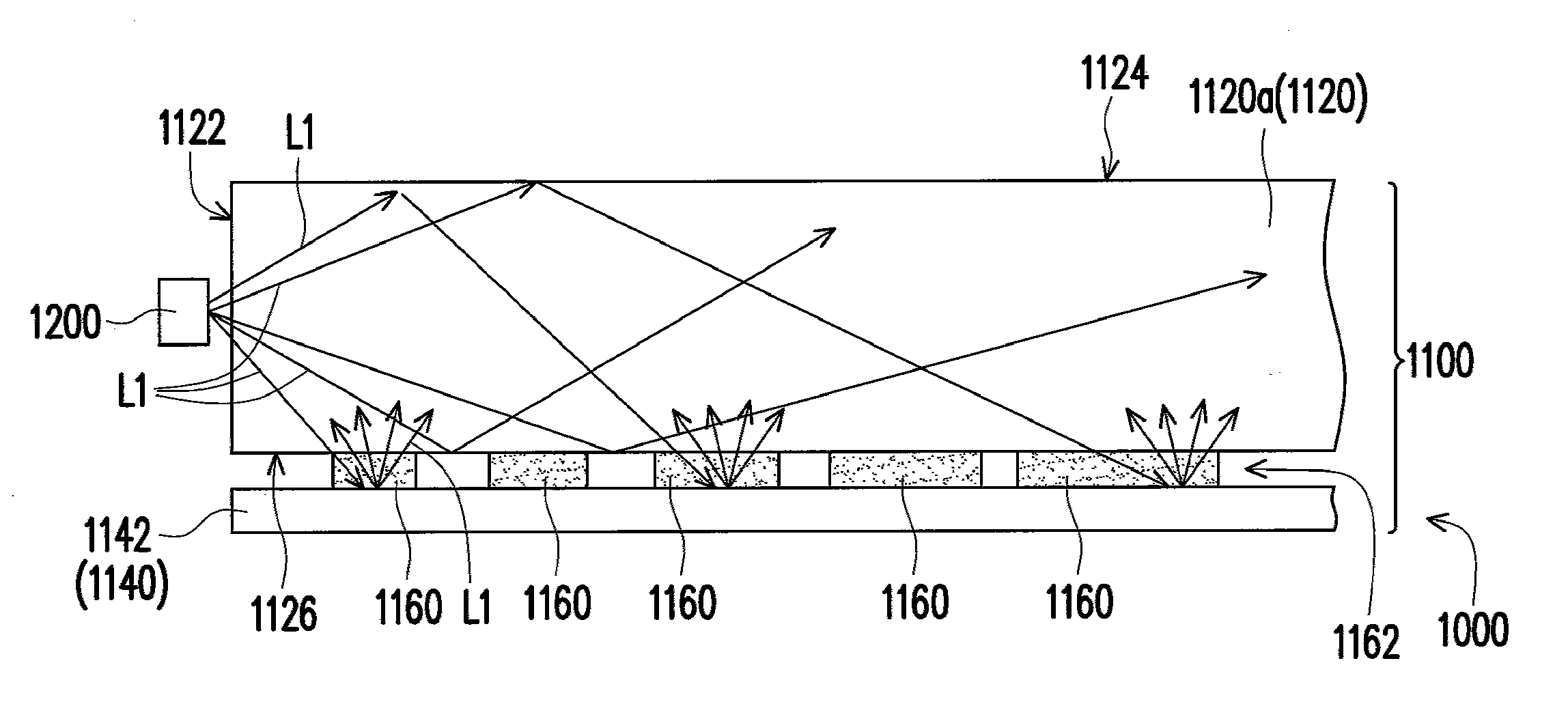
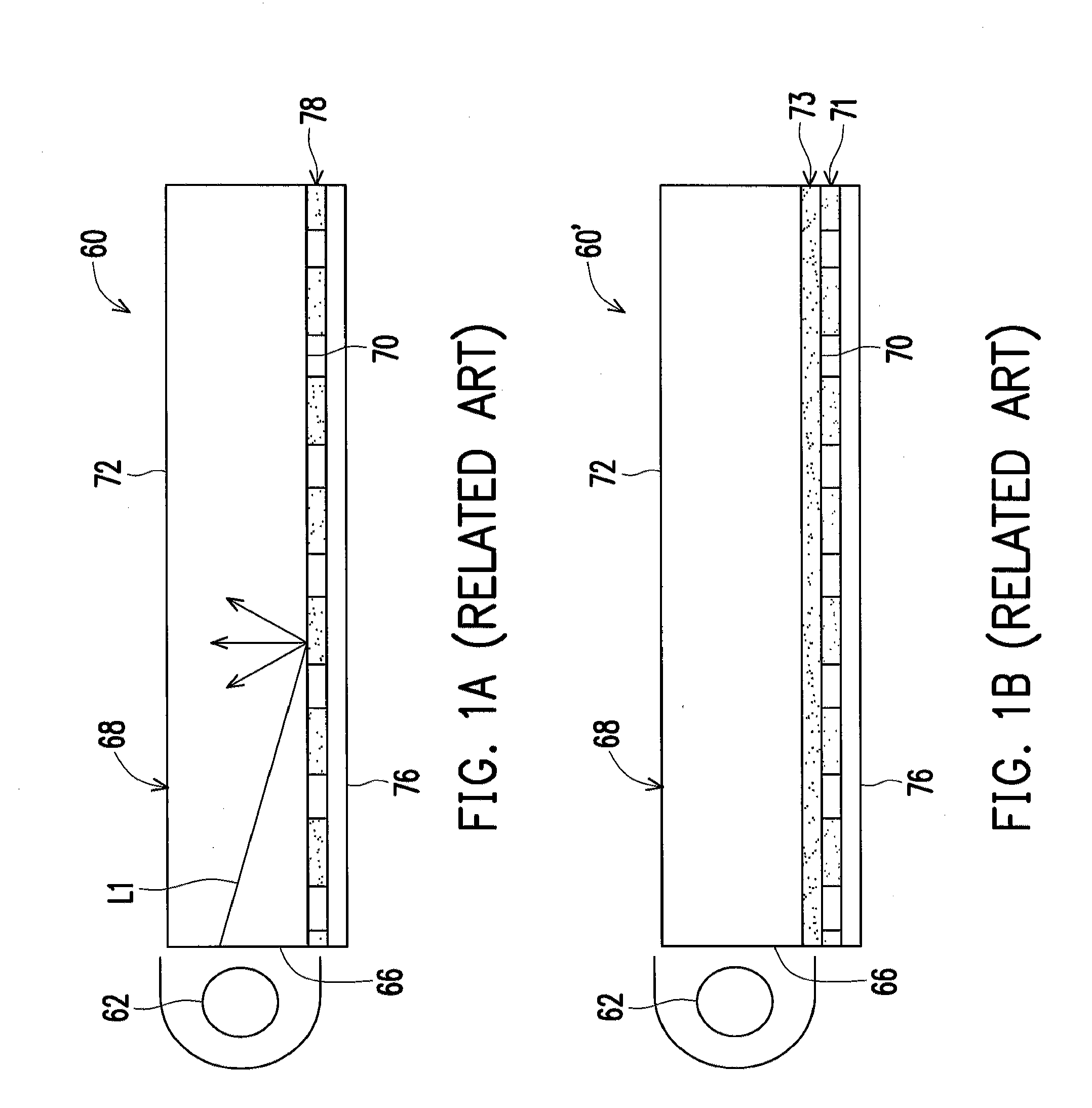
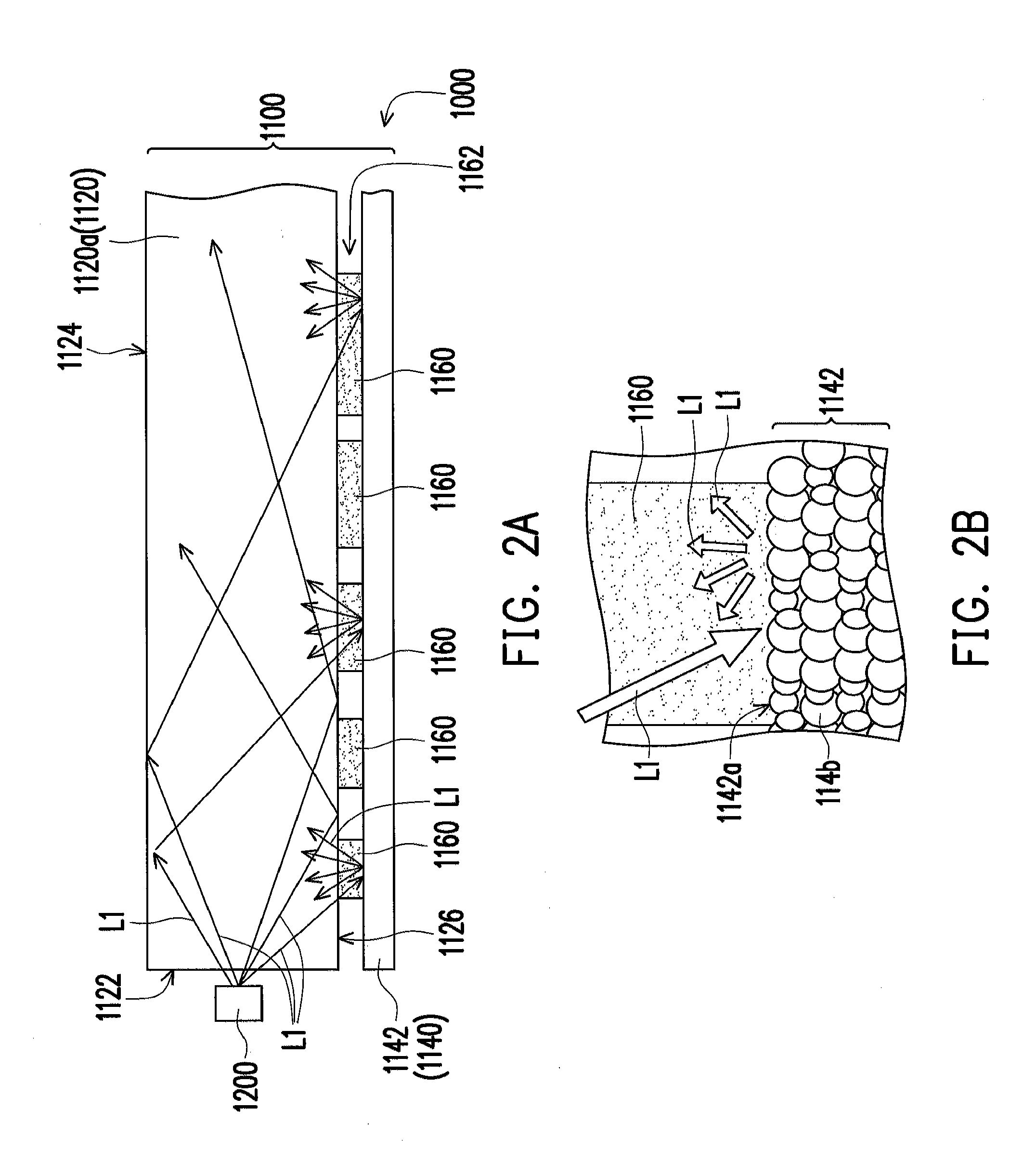
[0037]In the following detailed description of the preferred embodiments, reference is made to the accompanying drawings which form a part hereof, and in which are shown by way of illustration specific embodiments in which the invention may be practiced. In this regard, directional terminology, such as “top,”“bottom,”“front,” or “back,” etc., is used with reference to the orientation of the Figure(s) being described. The components of the present invention can be positioned in a number of different orientations. As such, the directional terminology is used for purposes of illustration and is in no way limiting. On the other hand, the drawings are only schematic and the sizes of components may be exaggerated for clarity. It is to be understood that other embodiments may be utilized and structural changes may be made without departing from the scope of the present invention. Also, it is to be understood that the phraseology and terminology used herein are for the purpose of descriptio...


PUM

PropertyMeasurementUnit
microstructuresaaaaaaaaaa
flexibleaaaaaaaaaa
refractive indexaaaaaaaaaa

Abstract

A light guide module includes a light guide plate and a diffuse reflector. The light guide plate has a light incidence surface, a light exiting surface, and a bottom surface, wherein the light exiting surface is opposite to the bottom surface, and the light incidence surface is connected with the light exiting surface and the bottom surface. The diffuse reflector is secured to the bottom surface of the light guide plate by an adhesive pattern layer, wherein the adhesive pattern layer is formed by a plurality of light-transmissive adhesive gels, and these light-transmissive adhesive gels do not contain any diffusive particles. A backlight module using the light guide module mentioned above and a fabricating method for the light guide module are also provided.

Description

CROSS-REFERENCE TO RELATED APPLICATION[0001]This application claims the priority benefit of Taiwan application serial no. 099142825, filed on Dec. 8, 2010. The entirety of the above-mentioned patent application is hereby incorporated by reference herein and made a part of this specification.BACKGROUND OF THE INVENTION[0002]1. Field of the Invention[0003]The invention relates to a light guide module and a fabricating method of the light guide module, more particularly to a backlight module having the light guide module, and a fabrication method thereof.[0004]2. Description of Related Art[0005]As shown in FIG. 1A, the backlight module 60 includes a light source 62, a light guide plate 68, a patterned adhesive layer 78, and a reflection sheet 76. The light guide plate 68 includes an incidence surface 66, a bottom surface 70, a light exiting surface 72, wherein the light source 62 is disposed beside the incidence surface 66 of the light guide plate 68. The reflection sheet 76 is secured...

Claims


Application Information

Patent Timeline
Patent Type & Authority Applications(United States)
IPC IPC(8): F21V8/00B32B38/14B32B37/14B32B37/12
CPCG02B6/0051Y10T156/10G02B6/0055
Inventor PAN, BO-CHIH
Owner YOUNG LIGHTING TECHNOLOGY INC
Why Eureka
Try Eureka