Electric motorized bicycle components and a wireless control system including such

Inactive Publication Date: 2012-06-14
BUCHHEIM JAMES
View PDF8 Cites 23 Cited by
  • Summary
  • Abstract
  • Description
  • Claims
  • Application Information

AI Technical Summary

Benefits of technology

[0007]The present invention is an electric motorized bicycle wheel having the power supply batteries mounted within compartme

Problems solved by technology

These wires add to the amount of time needed and the difficulty of initial insta

Method used


Image

  • Electric motorized bicycle components and a wireless control system including such
  • Electric motorized bicycle components and a wireless control system including such
  • Electric motorized bicycle components and a wireless control system including such

Examples


Embodiment Construction

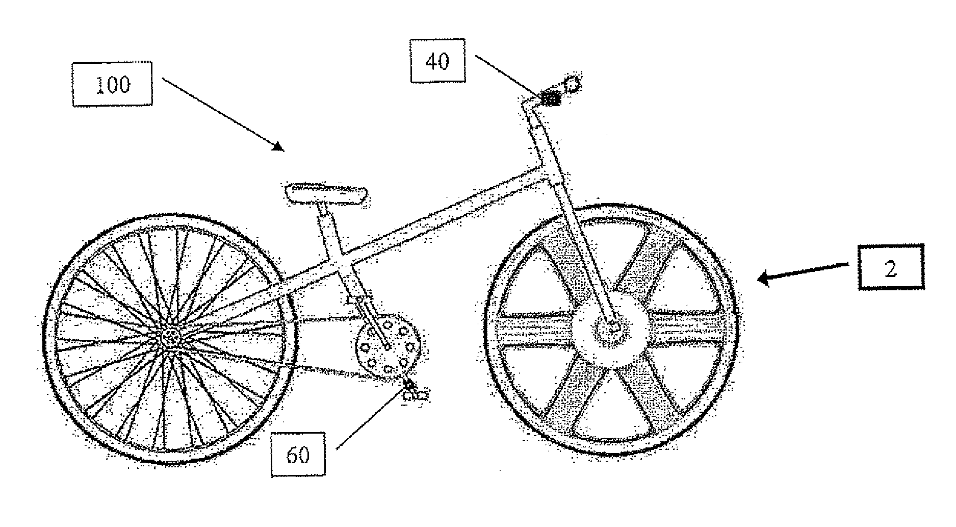
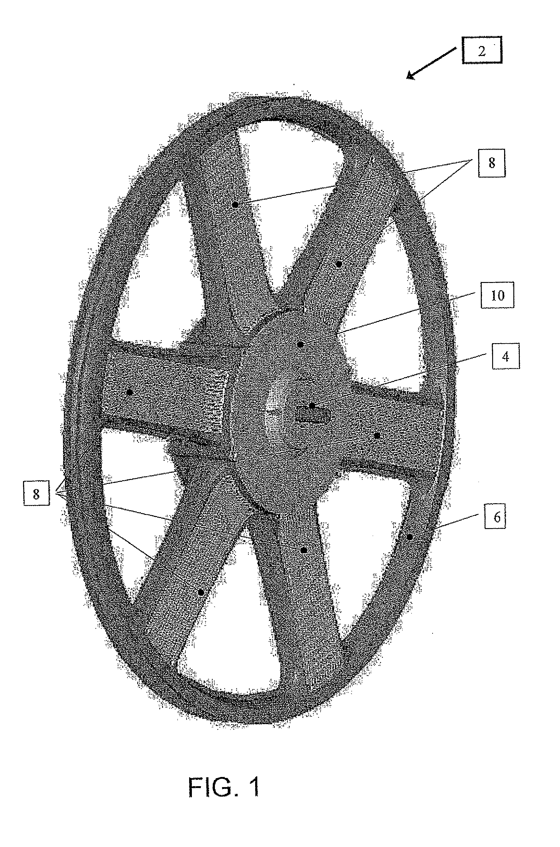
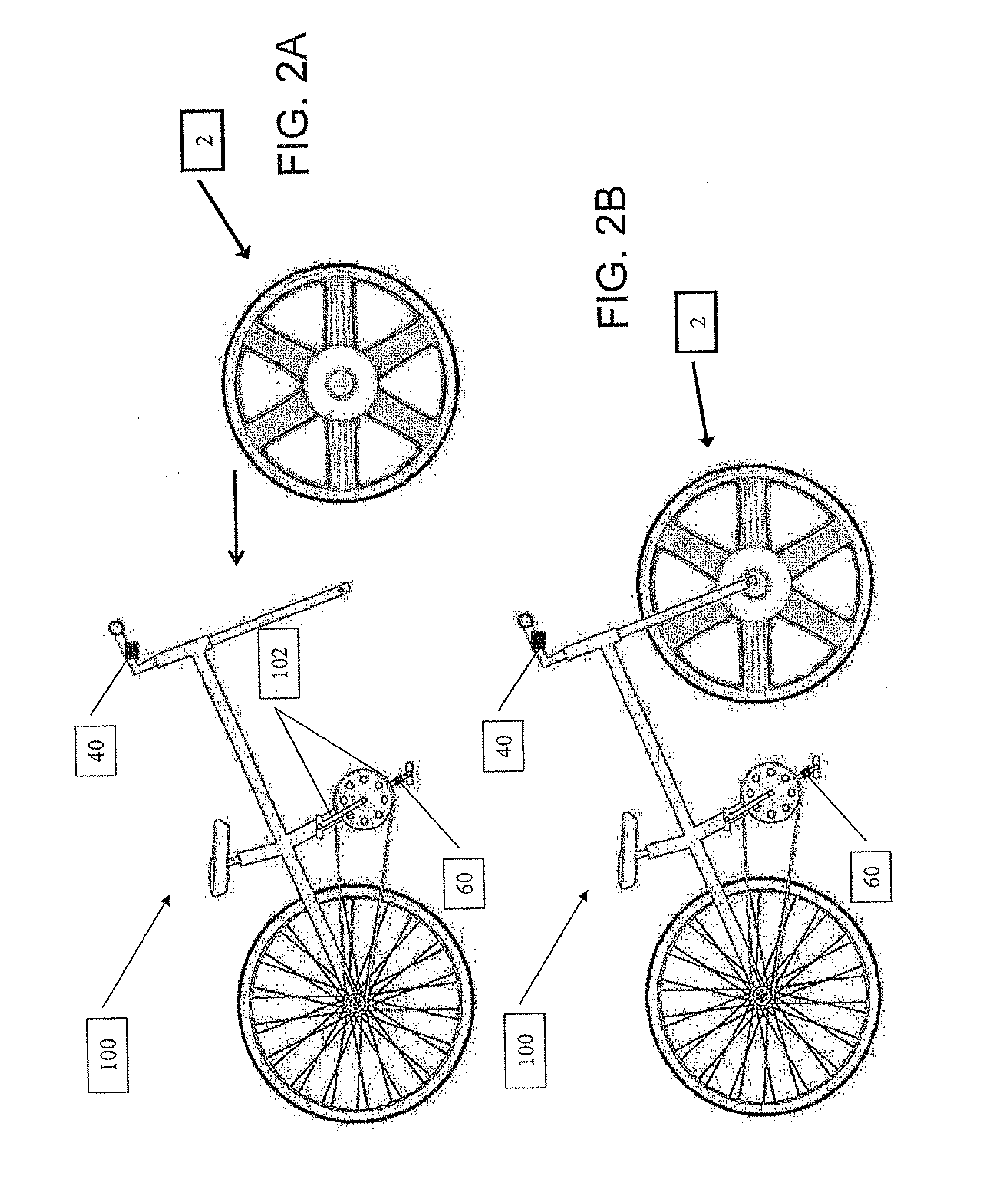
[0032]The present invention is an electric motorized bicycle wheel having the power supply batteries mounted within compartments configured in the spokes and a system including such a wheel together with a wireless speed control and / or a wireless PAS.

[0033]The principles and operation of electric motorized bicycle components according to the present invention may be better understood with reference to the drawings and the accompanying description.

[0034]By way of introduction, the electric components of the present invention when used together provide an unique electric power assist system the is well suited for use with bicycles, however, the features and principles of the present invention may be applied with equal benefit to wheels for use with other vehicles such as, but not limited to, wheel chairs, tricycles and even cars and motorcycles. Furthermore, each of the components may be used individually as well.

[0035]Referring now to the drawings, the illustrative example of an elec...


PUM


Abstract

An electric power assist system for use with a pedal vehicle. The system has (a) an electric motorized wheel (2) including a plurality of spokes (8) extending from the motor housing to the rim (6), at least one the spoke (8) configured so as to define within it a battery compartment (20) in which at least one power supply battery (22) is deployed, wherein the battery compartment (20) lies in the planer region substantially defined by the outer sides of the rim (6); (b) a wireless throttle control in RF communication with the wheel (2); and (c) a wireless pedal assist sensor in RF comunication with the wheel (12) and configured to deteect movement of the pedal vehicle and transmit command signals to the wheel so as to start power assist operation, and to stop the power assist operation as determined by the movement of the pedals.

Description

FIELD AND BACKGROUND OF THE INVENTION[0001]The present invention relates to motorized bicycle components and, in particular, it concerns an electric motorized bicycle wheel having the power supply batteries mounted within compartments configured in the spokes and a system including such a wheel together with a wireless speed control and / or a wireless PAS (pedal assist sensor).[0002]It is known to provide electric power assist bicycles with hub motors. Generally, wheels having hub motors are configured with conventional spokes or solid wheels.[0003]The versions having solid wheels typically utilize the empty space within the wheel shell for the deployment of components such as controllers and batteries. The majority of the wheel shell is wider than the rim of the wheel on which the tire is deployed.[0004]The versions having conventional spokes typically have such components deployed off the wheel or on special structures on the wheel whose sole purpose is to hold these components and...

Claims


Application Information

Patent Timeline
IPC IPC(8): B62M6/50B60K7/00B62M6/40
CPCB62M6/50B62M6/90B62M6/60B60B1/003B62M1/36B62M6/65H02J7/0018
Inventor BUCHHEIM, JAMESHENNIG, ARNEBRIGGS, JEREMY
Owner BUCHHEIM JAMES
Why Eureka
Try Eureka