Eureka AIR delivers breakthrough ideas for toughest innovation challenges, trusted by R&D personnel around the world.

Gear shift device for bicycles

A technology for bicycles and equipment, which is applied to bicycle gear transmission mechanisms, turning equipment, turning equipment, etc., and can solve problems such as insufficient assurance of sensor reliability

Inactive Publication Date: 2008-08-06
CAMPAGNOLO SRL
View PDF6 Cites 2 Cited by
  • Summary
  • Abstract
  • Description
  • Claims
  • Application Information

AI Technical Summary

Problems solved by technology

However, such a solution may not be sufficient to ensure the reliability of the sensor, because when the power is not supplied, the position of the second body of the derailleur may have small changes due to the vibrations that the bicycle is susceptible to during motion.

Method used


Image

  • Gear shift device for bicycles
  • Gear shift device for bicycles
  • Gear shift device for bicycles

Examples


Embodiment Construction

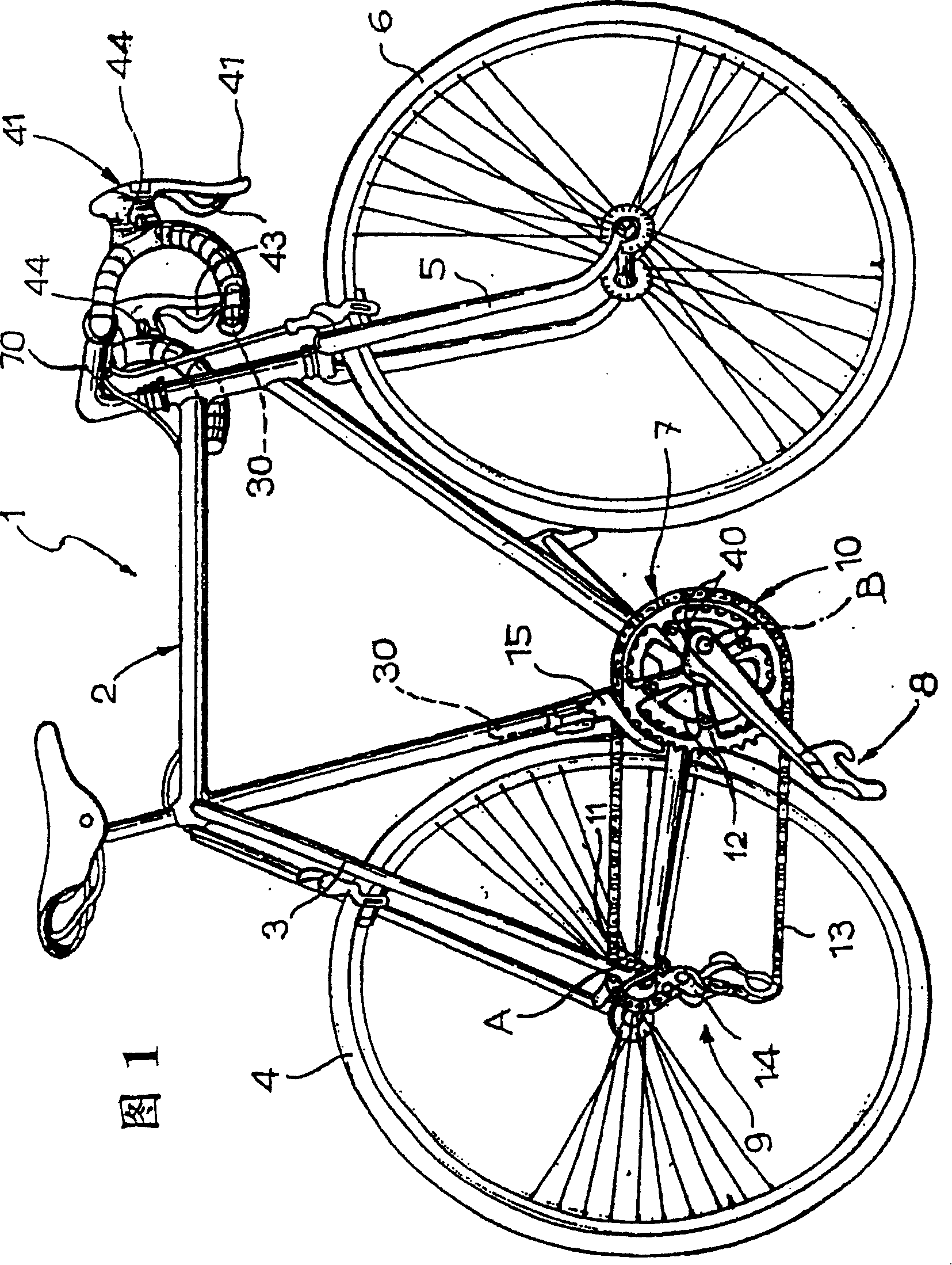
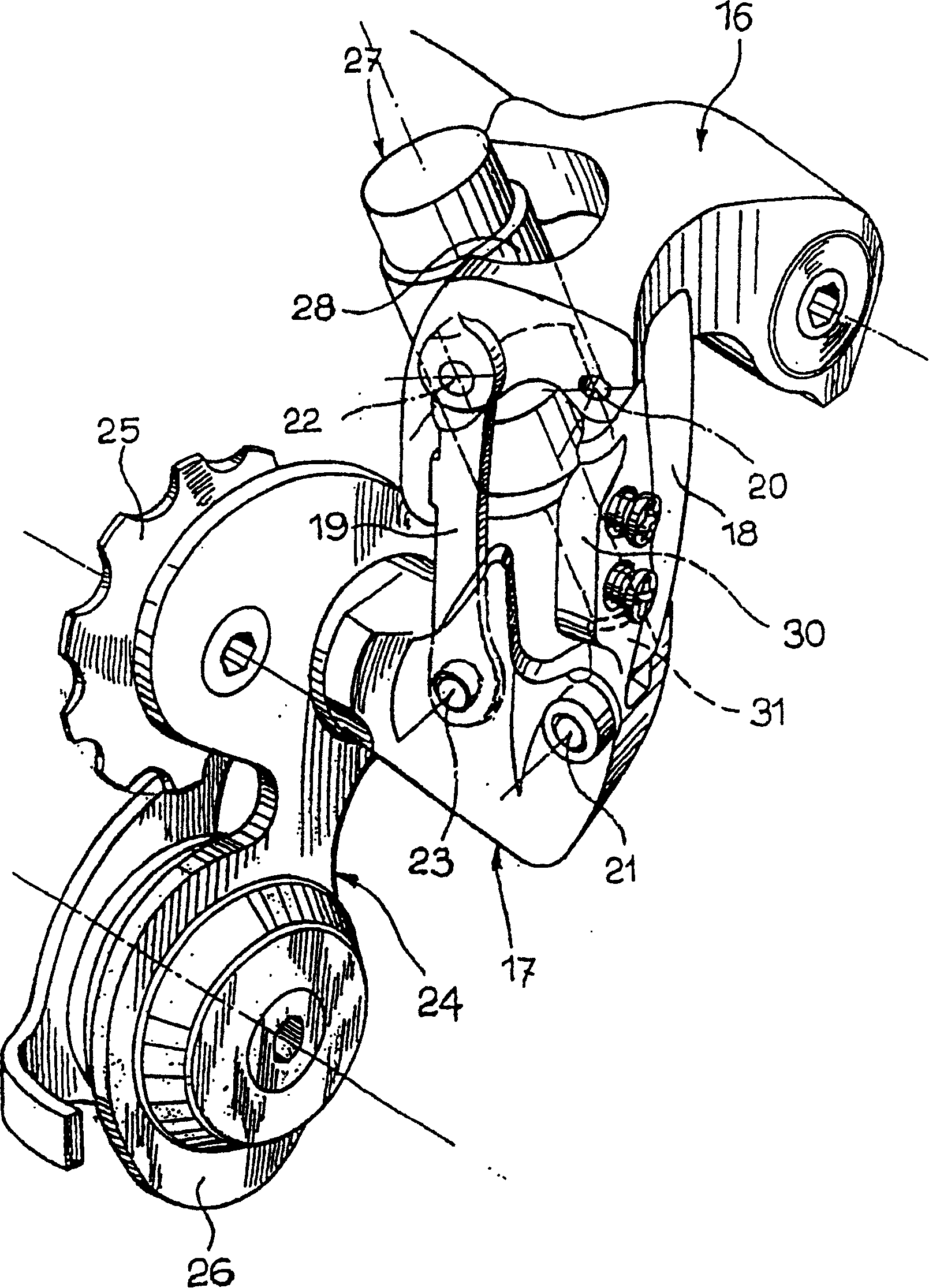
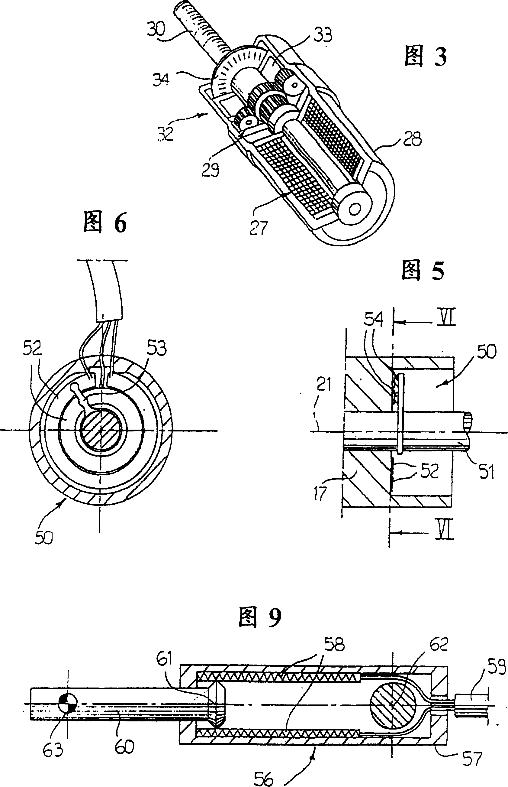
[0041] exist Figure 4 in, corresponding to figure 2 Parts shown in are denoted by the same reference numerals, in Figure 4 The general arrangement of the rear derailleur unit shown in is essentially the same as figure 2 same as shown in . Likewise, the motor and reduction gear assembly has a body 28 articulated at 22 with the first body 16 of the variator unit, and the assembly controls a screw 30 engaged with a nut 31 articulated at 21 with the second body 17 of the variator unit. hinged. but in Figure 4 In the case of , the means for detecting the position of the second main body 17 is not composed of an encoder connected to the motor 27, but consists of a sensor 50 installed in line with the hinge shaft 21 of the parallelogram linkage. More particularly, the sensor 50 is an absolute sensor, ie the sensor is designed to generate an electrical output signal indicative of the absolute position of the second body 17 . exist Figure 4 In the preferred embodiment, the sen...


PUM


Abstract

A motorized bicycle gear shift device comprising a derailleur (14) and an electric motor (27) for controlling the derailleur (14), associated directly with the derailleur, and an electric transducer of absolute type (50, 56), also associated with the derailleur (14) and designed to produce an electric signal indicative of the absolute position of the movable body (17) of the derailleur (14).

Description

Background technique [0001] The present invention relates to bicycle speed change equipment, this type of speed change equipment comprises: [0002] at least one derailleur device having a first body intended to be attached to a bicycle frame and having a second body displaceable relative to the first body to induce selectivity of a bicycle chain on a plurality of sprockets engagement, thereby obtaining different gear ratios of the device; [0003] an electric actuator for driving the displacement of the second body of the transmission device; [0004] an electronic control unit for controlling said electric actuator; [0005] manual activation means, connected to said electrical control means, activating said electrical actuator to select the desired gear; [0006] means for detecting the position of the second body of the variator means and indicating said position to said control means in order to automatically deactivate the electric actuator once the desired position h...

Claims


Application Information

Patent Timeline
IPC IPC(8): B62M9/12B62M25/08B62M9/122B62M9/132F16H59/04F16H61/28
CPCB62M9/132B62M9/122B62M25/08Y10T82/17Y10T82/16606
Inventor V·坎培诺洛
Owner CAMPAGNOLO SRL
Why Eureka
Eureka Blog
Learn More