Brake plate

a technology of brake pads and friction linings, applied in the field of brake pads, can solve the problems of heat and noise generation between the brake pads and the brake discs, unsatisfactory effects, and low cost efficiency of manufacturing methods

Inactive Publication Date: 2012-06-21
ITT MFG ENTERPRISES LLC
View PDF4 Cites 8 Cited by
  • Summary
  • Abstract
  • Description
  • Claims
  • Application Information

AI Technical Summary

Problems solved by technology

Friction between the brake pad and the brake disc generates heat and noise.
In particular, the latter effect is undesirable.
A brake pad provided with a non-structural friction layer provides some open issues relating to the cost efficiency of the manufacturing method because of the fact that the friction layer is substantially inconsistent, i.e. is a mix of organic & inorganic powders and a binder, before the heat and pressure treatment.

Method used


Image

  • Brake plate
  • Brake plate
  • Brake plate

Examples


Embodiment Construction

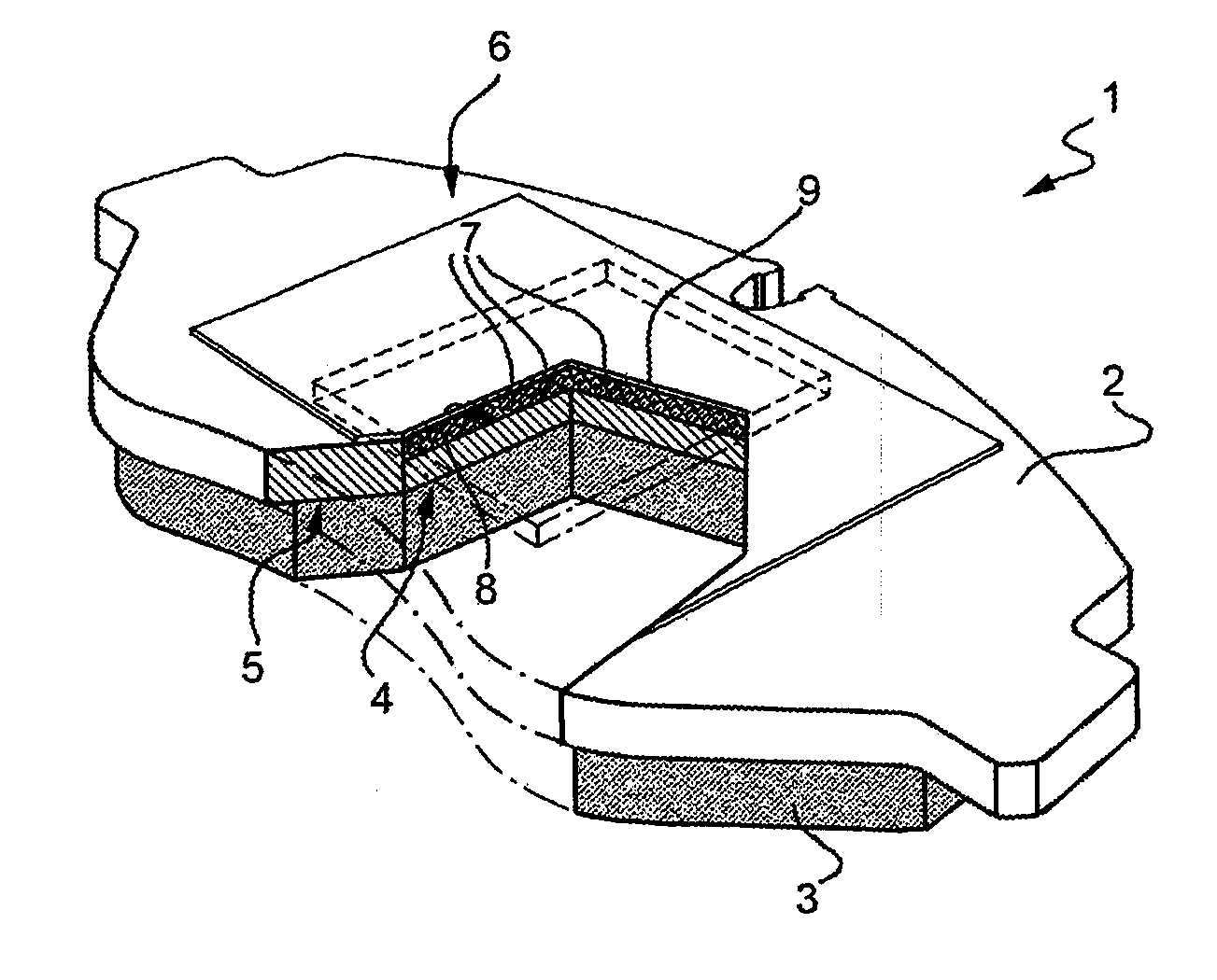
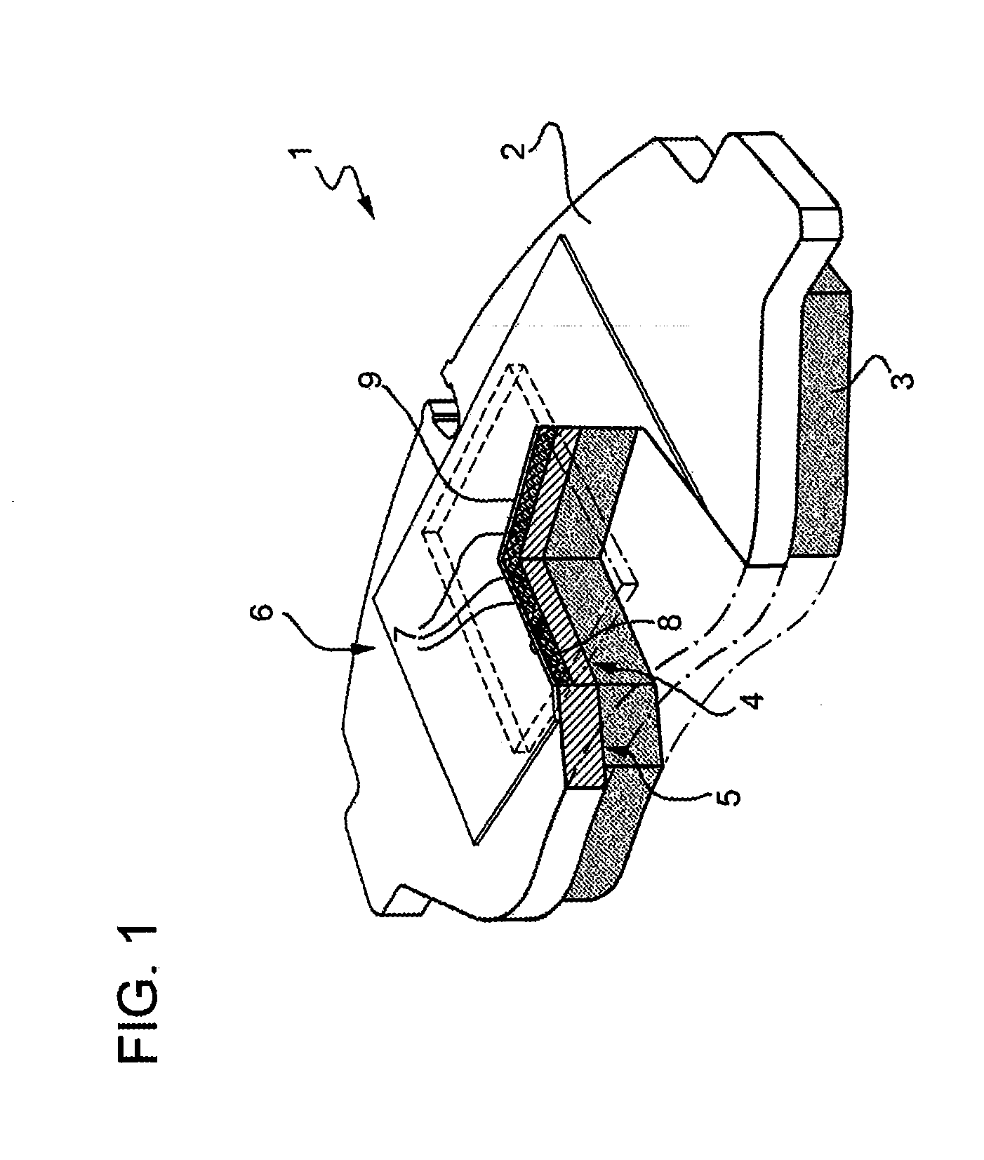
[0013]In FIG. 1 reference number 1 indicates as a whole a brake plate for a braking system of a motor vehicle, in particular a car or a motorbike.

[0014]Brake plate 1 comprises a back plate 2 made preferably of steel or cast iron, a friction layer 3 preferably sintered on back plate 2, and a particle damping device 4. Back plate 2 has a first surface 5 defining an interface with friction layer 3 and a second surface 6 opposite to first surface 5 and contacting known support elements of the braking system, such as pistons and calipers. Friction layer 3 is preferably a composite material constituted by a powder and matrix that needs to be heat treated, e.g. hot pressed or sintered, on back plate 2. Such a powder is a mix of different compounds, i.e. a mix of friction compounds, a mix of lubricant compounds, a mix of inert compounds, and a mix of metals. Therefore, the powder is a mix of organic and inorganic compounds. The matrix is preferably a polymeric compound, more preferably a ph...


PUM

PropertyMeasurementUnit
diameteraaaaaaaaaa
frictionaaaaaaaaaa
braking frictionaaaaaaaaaa

Abstract

A plate for a braking system of a motor vehicle includes a back plate, a friction layer and a particle damping device.

Description

BACKGROUND[0001]1. Technical Field[0002]The present disclosure relates to a brake pad for a breaking system, preferably for a motor vehicle.[0003]2. Description of the Related Art[0004]A brake pad cooperates with a brake disc to dissipate kinetic energy by friction and decrease the angular speed of the disc. In particular the disc can be rigidly connected to the wheel of a car or a motorcycle so that during braking the vehicle decelerates. In principle a brake pad consists at least of a rigid back plate or carrier and a layer of friction material.[0005]Friction between the brake pad and the brake disc generates heat and noise. In particular, the latter effect is undesirable.[0006]It is known from WO-A-0014425 to use a particle damping device in a braking system to avoid undesired noise. The above application relates to breaking pads made of a thermo-structural material, i.e. carbon-carbon composite. In particular, the friction layer is made of a carbon-carbon composite so that this ...

Claims


Application Information

Patent Timeline
Patent Type & Authority Applications(United States)
IPC IPC(8): F16D65/097B29C65/44F16D69/02
CPCF16D65/0006F16D65/0018F16D65/092F16F7/015F16D2065/1328F16D2250/00F16D69/04
Inventor SANTAMARIA RAZO, DIEGO A.MARTINOTTO, LUCADONZELLI, DANIELE
Owner ITT MFG ENTERPRISES LLC
Why Eureka
Try Eureka