Method for manufacturing a magnetic tape head using a tmr sensor

a technology of magnetic tape and tmr sensor, which is applied in the manufacture of head surfaces, instruments, data recording, etc., can solve the problems of saving considerable time and expense in the manufacture of tape heads, and achieve the effect of saving considerable time and expens

Active Publication Date: 2012-06-21
WESTERN DIGITAL TECH INC
View PDF1 Cites 77 Cited by
  • Summary
  • Abstract
  • Description
  • Claims
  • Application Information

AI Technical Summary

Benefits of technology

[0005]Because the ion milling defines the stripe height and also removes the first and second gap layers from the field region, there is no need for a second masking and milling operation to remove these gap layers in the field. This saves considerable time and expense in the manufacture of the tape head.

Problems solved by technology

This saves considerable time and expense in the manufacture of the tape head.

Method used


Image

  • Method for manufacturing a magnetic tape head using a tmr sensor
  • Method for manufacturing a magnetic tape head using a tmr sensor
  • Method for manufacturing a magnetic tape head using a tmr sensor

Examples


Embodiment Construction

[0013]The following description is of the best embodiments presently contemplated for carrying out this invention. This description is made for the purpose of illustrating the general principles of this invention and is not meant to limit the inventive concepts claimed herein.

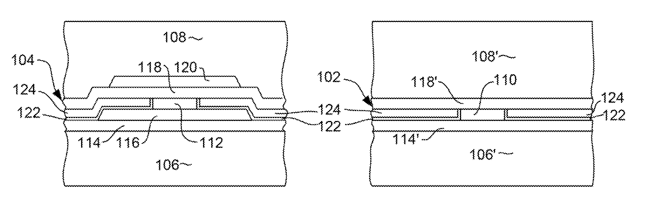
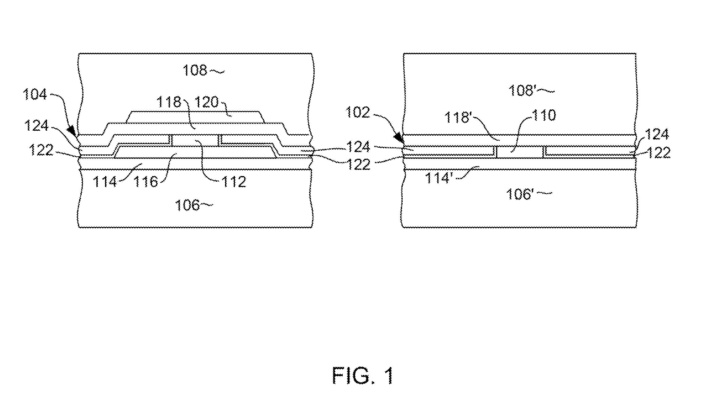
[0014]FIG. 1 shows an ABS view of a data read head 102 and a servo read head 104 both for use in a magnetic tape drive data recording system. In a tape drive system, a data head 102 and servo head 104 are both necessary, and are configure laterally aside one another on a common slider. In a tape drive system the desired read gap (i.e. shield to shield spacing) of a read head is determined by the magnetic spacing of the linear density, media thickness and spacing. If the gap is too large, there will be no high frequency signal. If it is too small, there will be a low overall signal. The optimal gap thickness for a typical tape drive is about 5 times that of a read head in a magnetic disk drive system.

[0015]With ...


PUM

PropertyMeasurementUnit
thicknessaaaaaaaaaa
thicknessaaaaaaaaaa
thicknessaaaaaaaaaa

Abstract

A method for manufacturing a magnetic tape head having a data sensor and a servo sensor. The data sensor and servo sensor are each separated from first and second magnetic shields by a non-magnetic gap layer, and the gap thickness for the servo sensor is larger than the gap thickness for the data sensor. The method involves depositing a first gap layer over shield structures, then depositing a second gap layer using a liftoff process to remove the second gap layer over the data sensor region. A plurality of sensor layers are then deposited, and a stripe height defining mask structure is formed over the data and servo sensor regions, the mask having a back edge that is configured to define a stripe height of the data and servo sensors. An ion milling is then performed to define the stripe height and to remove gap material from the field.

Description

FIELD OF THE INVENTION[0001]Embodiments of the present invention generally relate to tape modules used for magnetic recording on tapes, and more specifically to fabrication of servo and data head structures of a tape module.BACKGROUND OF THE INVENTION[0002]Tape modules are used to record information on tapes by magnetic processes. The tape modules use servo heads to read servo tracks to align the heads for reading data stored on data tracks. The servo heads and data heads are typically formed using a sensor disposed between two shield layers and directly contacting the two shield layers. However, current servo and data head designs do not provide adequate read-back in newer tape designs that require higher data densities as well as different servo track and data track densities. Additionally, the industry is moving to a tunneling magnetoresistive (TMR) sensor, which has a read gap defined by the TMR film. With current tape densities, a wider read gap is needed in both the data and s...

Claims


Application Information

Patent Timeline
Patent Type & Authority Applications(United States)
IPC IPC(8): G11B5/187
CPCG11B5/00826G11B5/3977G11B5/3909G11B5/3163
Inventor BROWN, DIANE L.LE, QUANGPARK, CHANG-MANSEAGLE, DAVID J.YAN, EILEEN
Owner WESTERN DIGITAL TECH INC
Why Eureka
Try Eureka