Drivers cab for a load-handling vehicle

a technology for drivers and load-handling vehicles, which is applied in the direction of vehicle bodies, loading-carrying vehicle superstructures, and monocoque structures. it can solve the problems of significant damage to the door or the machinery, the danger of personnel or other machinery coming into contact with the open door, and the known types of doors. it can achieve the effect of less space, less space, and constant overall width of the machin

Active Publication Date: 2008-09-30
MOFFETT RES & DEV
View PDF1 Cites 7 Cited by
  • Summary
  • Abstract
  • Description
  • Claims
  • Application Information

AI Technical Summary

Benefits of technology

[0012]In this way, by having a door that opens and closes by pivoting in its own substantially vertical plane, the door will no longer protrude outwardly from the vehicle when in an open position. The overall width of the machine will remain constant and the door will at no stage protrude outwardly from the vehicle. Therefore the door will present no danger to individuals and machinery in the vicinity of the vehicle whether the vehicle is stationary or moving. By pivoting in its own substantially vertical plane the door will furthermore not be inclined to move outwardly from the vehicle as a result of an impact from within the vehicle and will hold fast against any such impacts. This results in a more secure door for the operator of the vehicle. Furthermore, by mounting the door on one of the uprights, the door construction will be more compact and will require significantly less room on the vehicle than was previously the case and the door may be fitted onto practically any type of load handling vehicle including piggyback forklift trucks and the like. Finally, by mounting the door on one of the uprights, the door will also be easier to manufacture and valuable time will not be lost correctly positioning the door on the vehicle body.
[0013]In one embodiment of the invention there is provided a drivers cab in which the door is further provided with a releasable locking mechanism, the releasable locking mechanism being arranged to secure the door in position by releasably engaging the upright about which the door is pivotally mounted. This is seen as a particularly preferred aspect of the current invention. By having a locking mechanism that secures the door in position by releasably engaging the same upright about which the door is pivotally mounted, there will be no need for additional locking members to be mounted on a facing upright in order to secure the door in position. This saves considerable time and expense in the manufacture of the door as the positioning of the locking members is a time consuming and labour-intensive exercise. Furthermore, there will be less operating parts to the device making the construction simpler and less expensive than was previously possible. This is seen as a significant advantage over the previous devices.
[0014]In another embodiment of the invention there is provided a drivers cab in which the releasable locking mechanism further comprises a locking pin for bearing against the upright to prevent pivoting of the door and a handle connected to the locking pin, the locking pin being movable to and from a position bearing against the upright and a position free of the upright under operation of the handle. This is seen as a particularly simple construction that will be cost effective and simple to manufacture. The locking pin arrangement is reliable and is not prone to failure and by operating by simply bearing against the upright the device is extremely simple in construction and does not rely on intricate locking mechanisms to operate effectively.
[0029]By having a piggyback forklift truck of this construction, the piggyback truck will remain lightweight and will not require additional heavy components to mount the door in position. This is essential in piggyback forklifts as any increase in weight of the piggyback forklift leads to a proportional decrease in the possible carrying weight of the carrying vehicle. The overall width of the piggyback forklift will remain constant and the door will at no stage protrude outwardly from the vehicle. Therefore the door will present no danger to individuals and machinery in the vicinity of the vehicle whether the vehicle is stationary or moving. This also results in a more secure door for the operator of the piggyback forklift. Furthermore, by mounting the door on one of the uprights, the door construction will be more compact and will require significantly less room on the vehicle than was previously the case. This is also essential in piggyback forklifts in particular as space on these machines is always at a premium due to the fact that these machines are necessarily compact and lightweight for travelling on the rear of a carrying vehicle. Finally, by mounting the door on one of the uprights, the door will also be easier to manufacture and valuable time will not be lost correctly positioning the door on the vehicle body. This saves significantly on the manufacturing cost of the piggyback forklift truck.
[0032]In another embodiment of the invention there is provided a piggyback forklift in which the handle is located on the underside of the door body portion. By having the handle on the underside of the door, the driver of the vehicle will not inadvertently deactivate the locking mechanism should they accidentally fall against the door. This is seen as particularly useful in piggyback forklifts because due to the absence of counterweights in piggyback forklifts, these vehicles have more of a tendency to tilt to one side or another during a high speed turn of the vehicle thereby increasing the possibility of the operator being thrown against the door if they should turn the vehicle too quickly. By having the handle in this position, the operator will not therefore be prone to inadvertently opening the door when they are thrown against the door.

Problems solved by technology

There are however problems associated with the known types of doors.
When the door is in a fully open position, the door typically protrudes outwards from the drivers station to such an extent that there is a danger that personnel or other machinery could come into contact with the open door.
This often results in either significant damage to the door or the machinery and in certain situations this may result in injury to the personnel even when the vehicle is stationary.
It has been known in the past for such load-handling vehicles to be operated with the door in an open position, either deliberately or accidentally, which has resulted in serious injury to individuals and machinery impacted by the open door.
Another problem with the known types of door generally is that the doors, by their very nature, have a tendency to swing outwardly when a significant force is exerted on the door from within the driver's cab.
It has been known for these doors to inadvertently open as a result of the driver being thrown against the door in the event of a high speed turn or an accident.
Often, the driver's weight alone impacting against the door will be sufficient to cause the door to open and in other circumstances the driver will accidentally disengage the locking mechanism on the door as he or she is thrown against the door.
It is at these times when the door is most needed that it is most likely to fail.
Opening of the door in these circumstances has been known to result in serious injury to the drivers of the vehicle.
This has resulted in the requirement for more and more elaborate and expensive locking mechanisms being provided with these doors.
Typically, at least a portion of these elaborate locking mechanisms is mounted on an upright opposite the upright about which the door is mounted thereby requiring additional assembly which substantially increases the cost and complexity of manufacture of the vehicles.
Although this door will not pivot outwards when being opened, it requires a significant amount of space to be mounted on a vehicle and is only practical on the largest earthmoving machines and the like.
This door would not be practical in smaller load-handling vehicles and in particular piggyback forklifts where space is at an absolute premium.
A further disadvantage of this type of door is that it also requires a complimentary locking mechanism provided on an upright that entails additional manufacturing expense and complexity.

Method used


Image

  • Drivers cab for a load-handling vehicle
  • Drivers cab for a load-handling vehicle
  • Drivers cab for a load-handling vehicle

Examples


Embodiment Construction

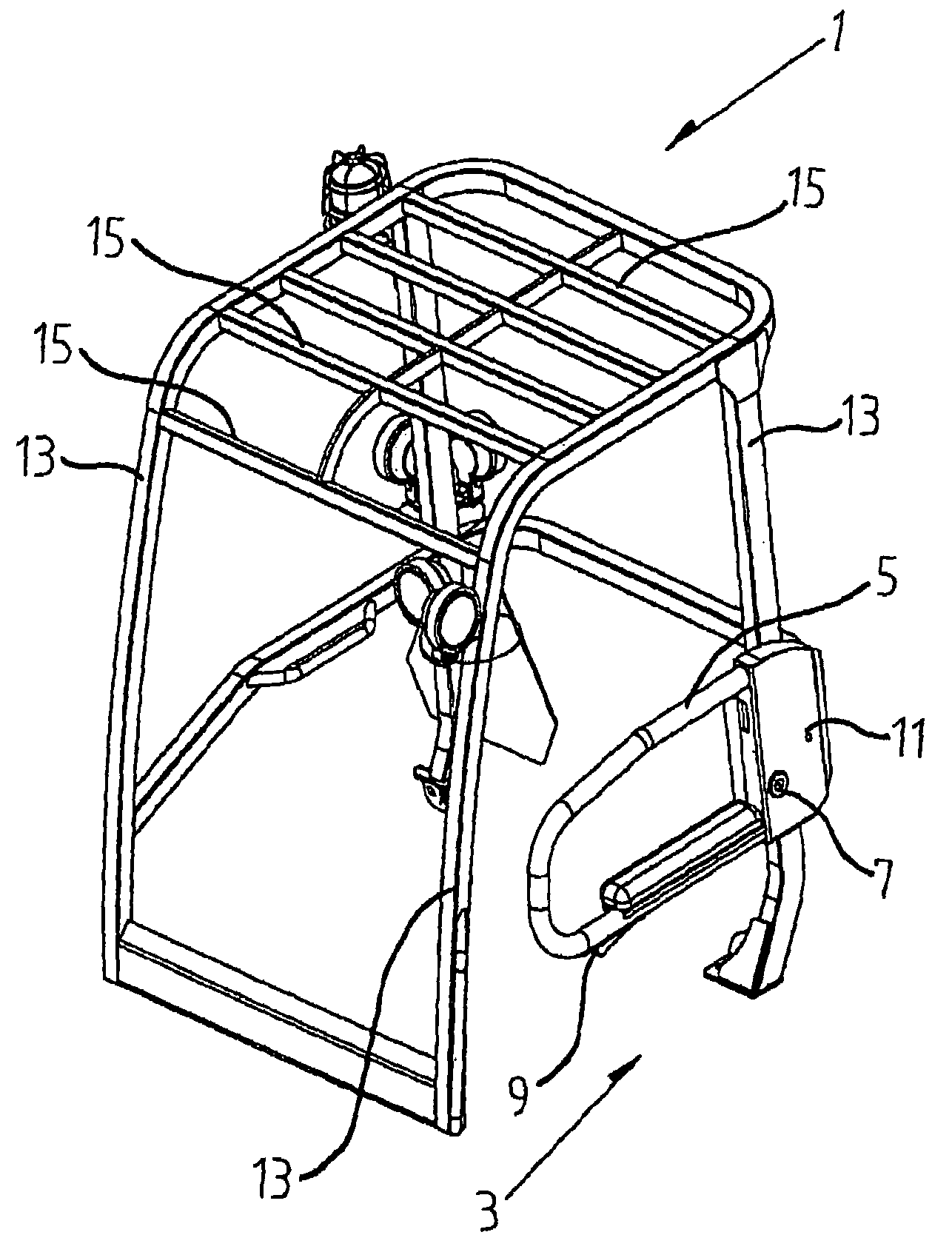
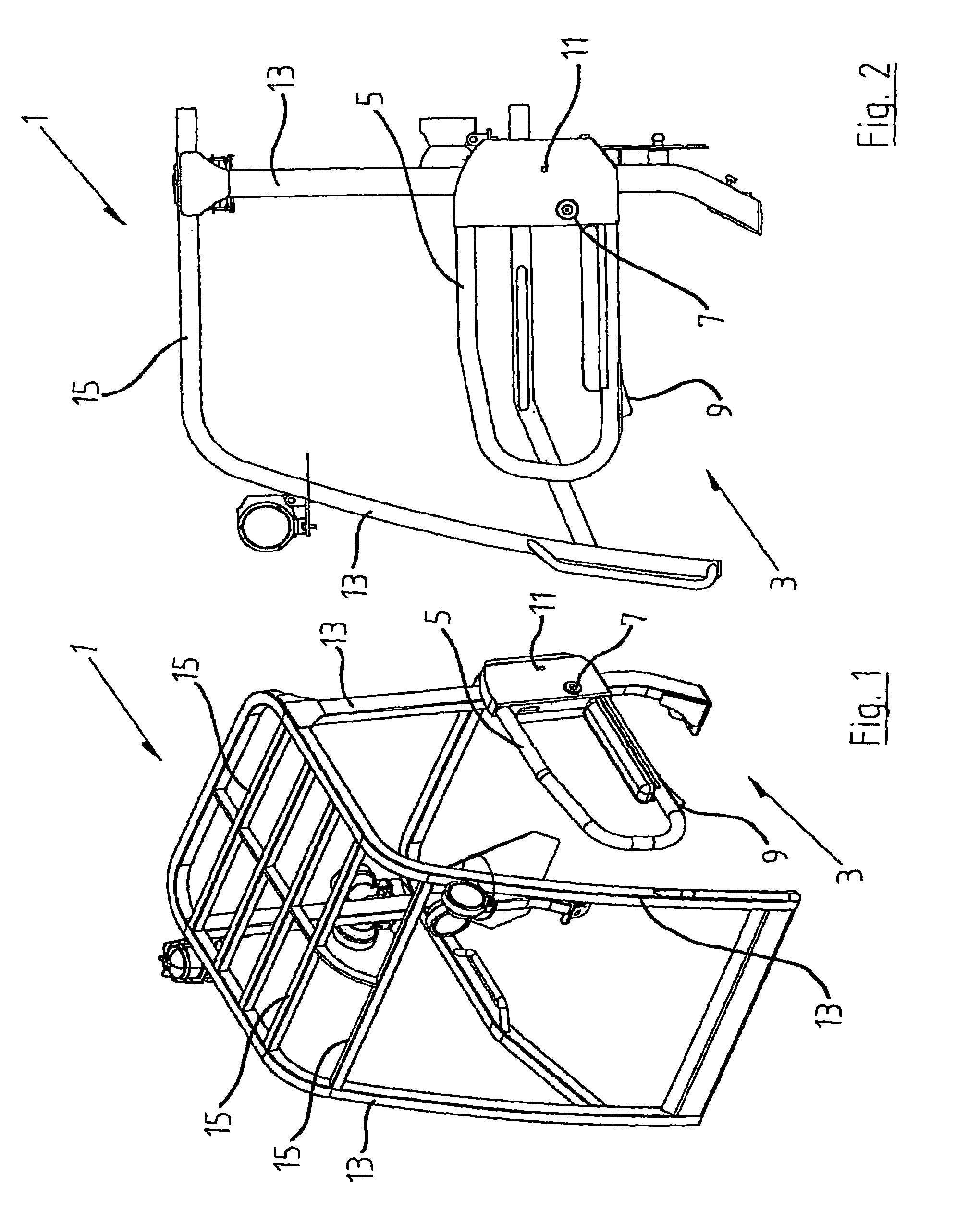
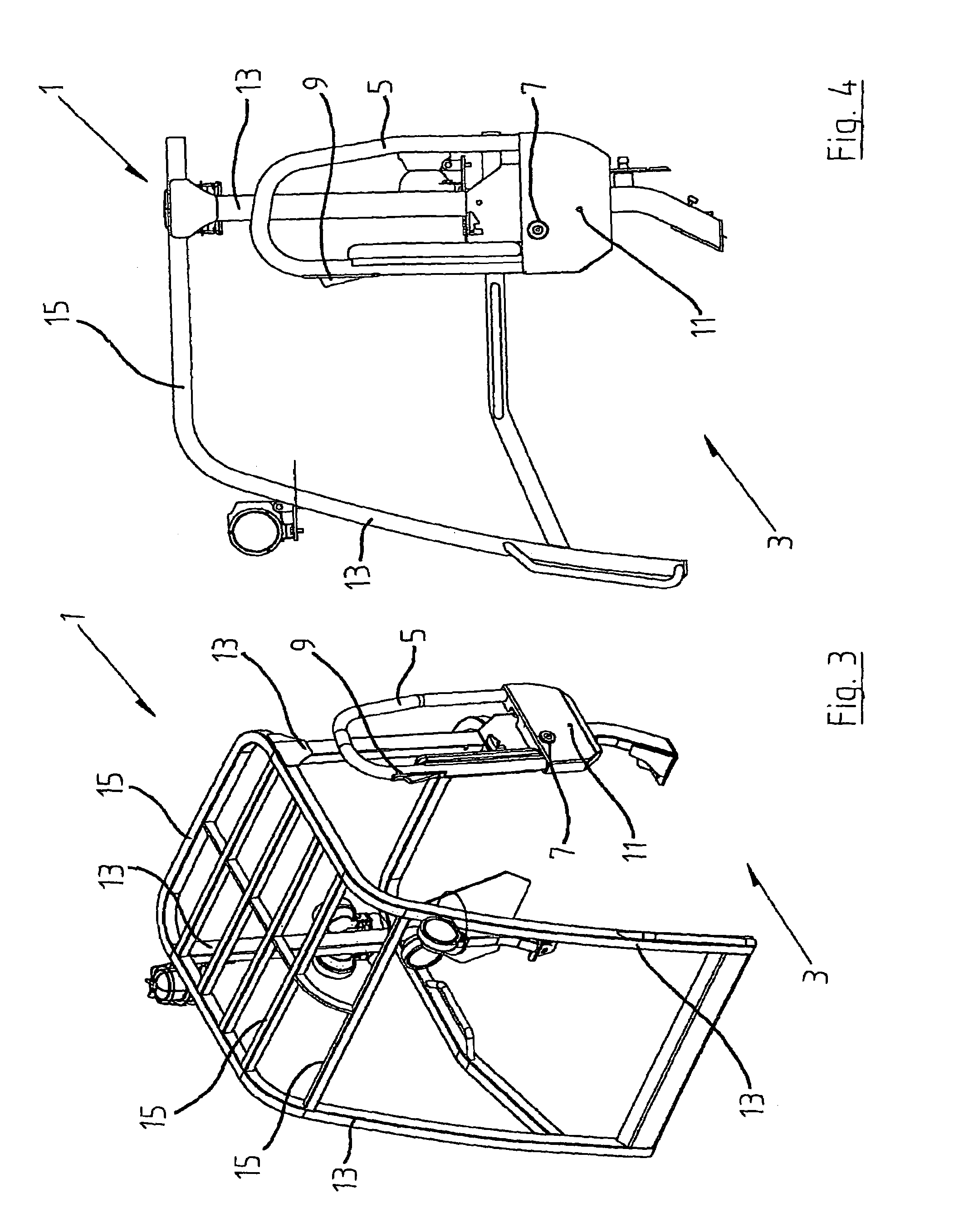
[0043]Referring to the drawings, and initially to FIGS. 1 to 4 inclusive, there is shown a driver's cab, indicated generally by the reference numeral 1, having an opening 3 to allow access to and from the cab and a door 5 mounted on the cab 1 and moveable to and from an open position in which the door is free of the opening (FIG. 3) and a closed position in which the door is across the opening (FIG. 1) thereby preventing access to or from the cab. The door 5 is pivotally mounted to the cab 1 about pivot pin 7 in such a manner so that the door pivots substantially in its own substantially vertical plane and does not protrude laterally outwardly from the cab when in an open position. Instead, the door pivots upwardly along its substantially vertical plane to the open position and remains in the same substantially vertical plane as in the closed position.

[0044]A locking mechanism comprising a release handle 9 and a locking pin 11 are provided on the door. The release handle 9 is operab...


PUM


Abstract

There is provided an alternative construction of driver's cab (1) for a load-handling vehicle and in particular an alternative construction of door (5) for a driver's cab. The door (5) is pivotally mounted on one of the uprights (13) of the driver's cab (1) and does not protrude outwardly from the driver's cab when opened or closed. The door (5) is mounted so that it effectively pivots about its own substantially vertical plane. The door (5) is provided with a locking mechanism that allows the door to be secured in position relative the upright (13) without the need for additional locking members being mounted on another of the uprights (13) on the driver's cab. The construction of driver's cab is lightweight and compact and allows for a more simplified manufacture by virtue of the omission of additional components.

Description

TECHNICAL FIELD OF THE INVENTION[0001]This invention relates to a drivers cab for a load-handling vehicle comprising a cage-like structure having a plurality of uprights bridged at their upper ends by a roof structure, the drivers cab having an opening for providing access to and from the drivers cab and a door moveable to and from an open configuration free of the opening thereby permitting access to and from the drivers cab through the opening and a closed configuration substantially across the opening thereby preventing access to and from the drivers cab.BACKGROUND OF THE INVENTION[0002]Load-handling vehicles, including forklift trucks, piggyback forklift trucks and other similar type vehicles are commonly used throughout the world. These vehicles are generally used for the movement of goods in a factory or for the movement of materials about a site. Typically, these vehicles are provided with a driver's station, otherwise referred to as a driver's cab, which is positioned either...

Claims


Application Information

Patent Timeline
Patent Type & Authority Patents(United States)
IPC IPC(8): B60J7/00
CPCB60J5/0487
Inventor TURNBULL, KEVINMCGRANE, BARRY
Owner MOFFETT RES & DEV
Why Eureka
Try Eureka