
Power Generating and Distribution System and Method

a power generation and distribution system technology, applied in the direction of transportation and packaging, inductances, and cosmonautic vehicles, can solve the problems of increasing the cost of transportation both to install and maintain, progressive exhaustion of readily accessible fossil fuel resources, and increasing obstacles for independent oil companies to maintain access to significant natural reserves. , to achieve the effect of reducing or eliminating pollution of the atmosphere, reducing or eliminating the cost of fossil fuel recovery

Active Publication Date: 2012-06-21
CRISWELL DAVID R DR
View PDF1 Cites 35 Cited by
  • Summary
  • Abstract
  • Description
  • Claims
  • Application Information

AI Technical Summary

Benefits of technology

"The present invention provides a new and improved energy transportation system for redistributing energy from one Earth-based location to another. The system includes a source of electricity, a microwave transmitter for converting the electricity into microwave beams, and a redirector satellite for receiving and redirecting the beams. The system can also include a beam redirector satellite in high orbits around the Earth or the Moon for directing the microwave beams to specific targets. The system reduces the cost of producing and distributing electricity, avoids the need for long distance transportation of fuel, and provides faster and more efficient energy transfer. The invention also includes a unified power-generating and distributing system that combines power extracting, converting, and transmitting facilities with a source of fossil fuel."

Problems solved by technology

Independent oil companies face increasing hurdles to maintaining access to significant natural reserves of oil and natural gas, due to the geopolitical distribution of such resources.
Such transportation is expensive both to install and maintain, and is potentially dangerous as a result of accidents, sabotage or terrorism.
Finally, progressive exhaustion of readily accessible fossil fuel resources requires exploration to attempt to find new sources of such fuels.
The struggle to locate and develop new sources of gas and oil will increase in difficulty over time, as such resources continue to be depleted by world power demands and population increases.
This has resulted in progressively higher prices and shortages in the power supply to the world population, and this problem is expected to become worse with time.
One potential problem with initial construction of a lunar based solar power collection and transmission system is the cost of deploying the necessary equipment to the Moon and establishing the solar power stations on the Moon.

Method used


Image

  • Power Generating and Distribution System and Method
  • Power Generating and Distribution System and Method
  • Power Generating and Distribution System and Method

Examples


Embodiment Construction

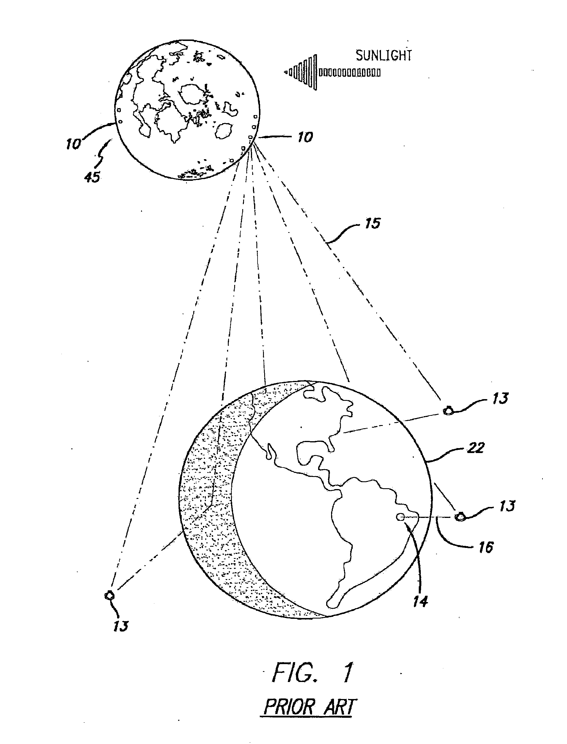
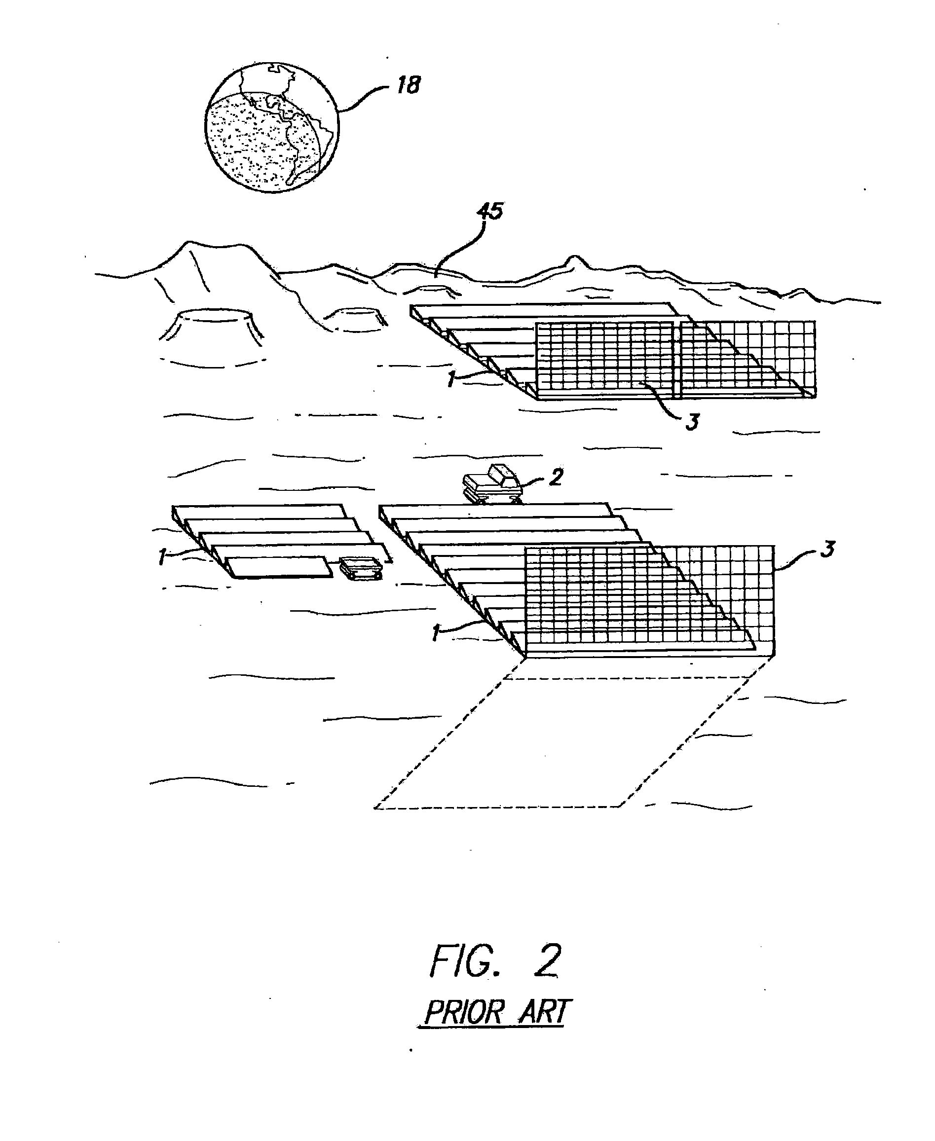
[0046]FIGS. 1 and 2 are schematic illustrations of a prior art power collection and transmission system as described in my U.S. Pat. Nos. 5,019,768 and 5,223,781, the contents of which are incorporated herein by reference. As illustrated in FIG. 1, solar power collecting and microwave transmitting stations 10 are provided on the Moon 45, and transmit microwave power beams 15 to orbiting redirectors 13 from which the beams 16 are transmitted onto selected small receiver or rectenna stations 14 on Earth 22. FIG. 2 illustrates an exemplary solar power collecting and microwave transmitting station on the Moon. The station comprises photovoltaic arrays or solar collectors 1, microwave transmitters 2, and a microwave reflective screen 3, as well as buried wiring.

[0047]With reference to FIG. 2, for the purpose of this application the term “far side” as applied to a first celestial body such as the Earth 18 or the Moon 45 means to the side which faces away from a second body or a specific l...


PUM


Abstract

A power distribution network is provided comprising ground-based microwave transmitters, receivers and microwave redirectors. The ground-based microwave transmitters have their own directional, focus and amplitude controllers for aiming a focused microwave beam at a microwave redirector. The microwave redirectors each have a receiving antenna and a plurality of transmitting antennae such that the redirectors transmit focused microwave beams to at least two different stations (for example, being either ground-based microwave receivers or other microwave redirectors).

Description

CROSS-REFERENCES TO RELATED APPLICATIONS[0001]This application is a Continuation In Part of U.S. application Ser. No. 13 / 013,791 now U.S. Pat. No. 8,074,936 filed Jan. 25, 2011 which is a Continuation of U.S. application Ser. No. 11 / 184,158, now U.S. Pat. No. 7,900,875, filed Jul. 18, 2005 which claims the benefit of priority of U.S. provisional Applications Ser. No. 60 / 589,919 filed Jul. 20, 2004, and Ser. No. 60 / 602,772 filed Aug. 19, 2004, the contents of both of which are incorporated herein by reference in their entirety. This application also claims priority to U.S. Provisional patent application 61 / 530,294, filed Sep. 1, 2011.BACKGROUND OF THE INVENTION[0002]The present invention is directed to a method and system for generating power and distributing the power to populated areas where it is needed, and to the use of the method to enable the deployment of a lunar solar power system by means of electric energy from Earth in support of a transportation system between the Earth,...

Claims


Application Information

Patent Timeline
Patent Type & Authority Applications(United States)
IPC IPC(8): H02J17/00
CPCB64G1/428H02J17/00B64G1/44H02J50/23H02J50/27H02J50/80H02J50/90B64G1/4282
Inventor CRISWELL, DAVID R.PETERSEN, JORI L.
Owner CRISWELL DAVID R DR
Learn More