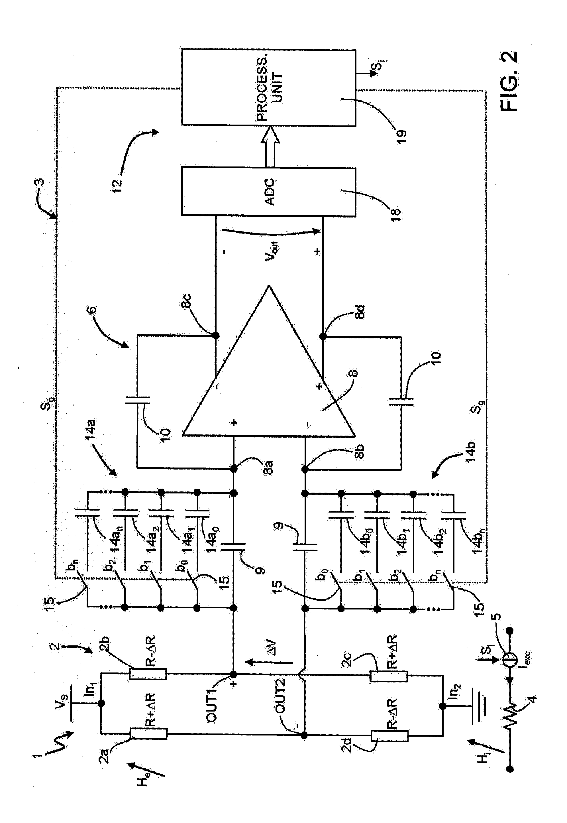
[0019]In an embodiment, a reading circuit for a magnetic-field sensor, said magnetic-field sensor being designed to generate an electrical detection quantity as a function of a detected magnetic field and of a detection sensitivity, comprises an amplification stage, coupled to said magnetic-field sensor and configured to generate an output signal as a function of said electrical detection quantity and of an amplification gain, wherein said amplification gain is electronically selectable, and by comprising a calibration stage, integrated with said amplification stage and configured to vary a value of said amplification gain so as to compensate for a variation of said detection sensitivity with respect to a nominal sensitivity value. In an embodiment, said calibration stage is configured to: detect at least one value associated to said output signal upon detection, by said magnetic-field sensor, of a controlled magnetic field, of a known value; determining an effective value of said detection sensitivity, as the result of said variation of sensitivity, as a function of said value associated to said output signal; and varying the value of said amplification gain based on said effective value of said detection sensitivity. In an embodiment, said magnetic-field sensor is provided with at least one first magnetoresistive element and with a magnetization element operatively coupled to said at least one first magnetoresistive element; and wherein said calibration stage is configured so as to cause generation of said controlled magnetic field as the result of an excitation current sent through said magnetization element. In an embodiment, said calibration stage is configured to: acquire at least a first value of said output signal, in the presence of an external magnetic field and in the absence of said controlled magnetic field; acquire at least a second value of said output signal, in the presence both of said external magnetic field and of said controlled magnetic field; and jointly process said first and second values of said output signal in order to determine said effective value of said detection sensitivity. In an embodiment, said calibration stage is configured to determine a difference between said first value and said second value of said output signal in order to determine said effective value of said detection sensitivity as a function of the value of said controlled magnetic field, irrespective of the value of said external magnetic field. In an embodiment, said amplification stage comprises an amplifier unit, having at least one input designed to receive said electrical detection quantity and at least one output designed to supply said output signal; and wherein said calibration stage comprises a gain-variation unit, coupled to said amplifier unit and configured to vary a gain thereof between the input and the output. In an embodiment, said amplifier unit comprises a gain network, coupled to said at least one input and to said at least one output, and said gain-variation unit comprises an adjustable-impedance unit, which is coupled to said gain network and has a selectable impedance value; and wherein said calibration stage is configured to provide a gain-control signal to said gain-variation unit for selecting the value of said impedance. In an embodiment, said magnetic-field sensor is an AMR magnetic sensor provided with further magnetoresistive elements, arranged with said at least one first magnetoresistive element to form a bridge detection structure; wherein said electrical detection quantity is a unbalancing signal of said bridge detection structure. In an embodiment, an electronic device comprises a magnetic-field sensor, and a reading circuit, coupled to said magnetic-field sensor, said electronic device further comprising a control unit, coupled to said reading circuit for receiving said output signal. In an embodiment, said reading circuit is made as an ASIC (application-specific integrated circuit), and is housed in a same package together with a die integrating said magnetic-field sensor.
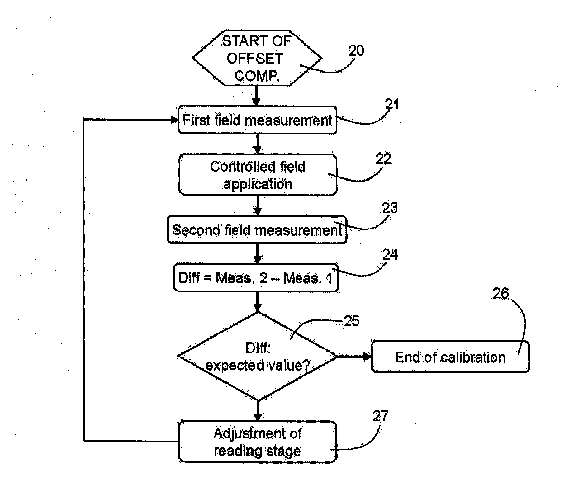
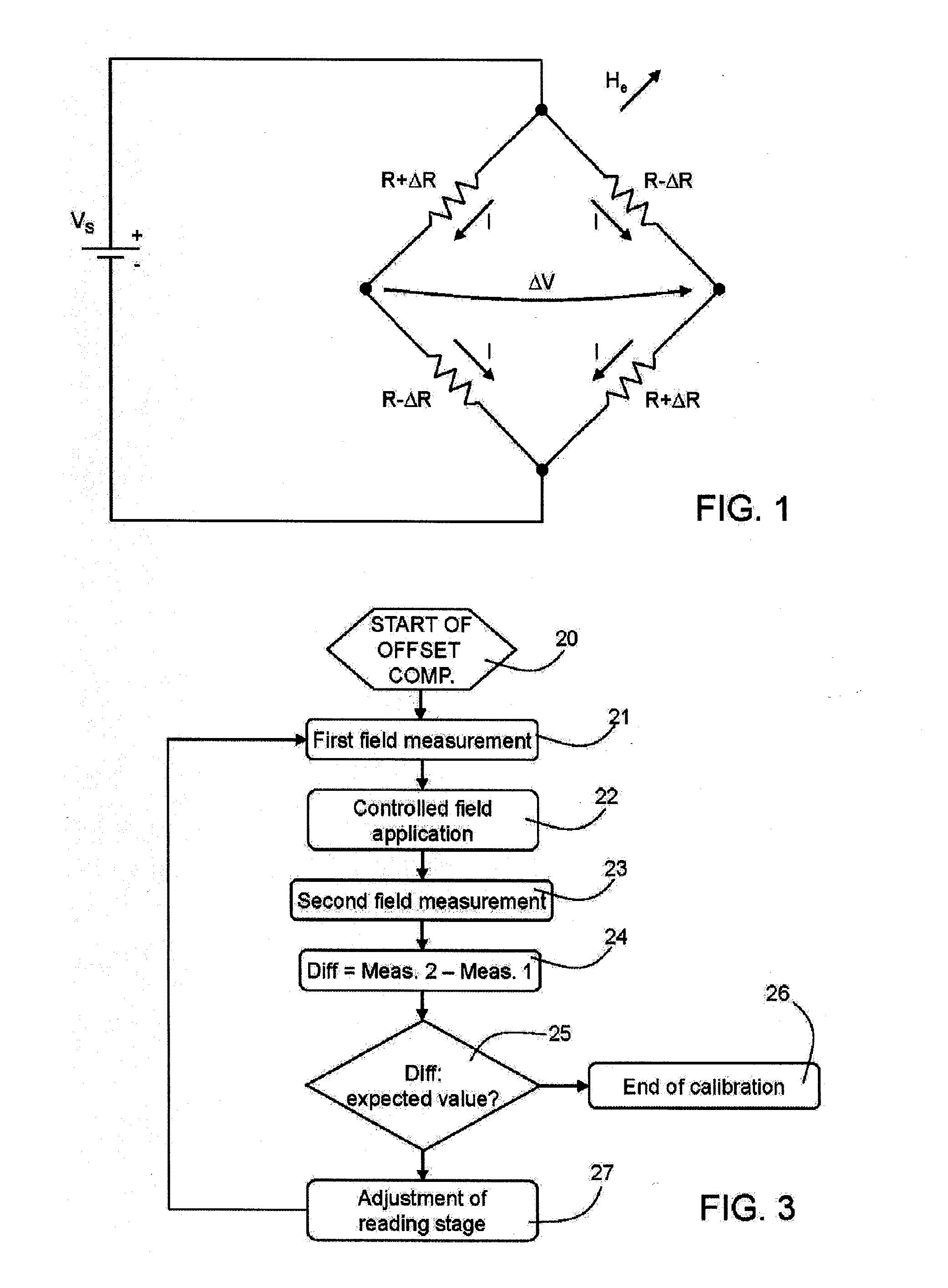
[0020]In an embodiment, a method for reading a magnetic-field sensor, said magnetic-field sensor being designed to generate an electrical detection quantity as a function of a detected magnetic field and of a detection sensitivity, comprises the step of generating, by means of a reading circuit, coupled to said magnetic-field sensor and having an amplification gain, an output signal as a function of said electrical detection quantity and of said amplification gain, and varying a value of said amplification gain so as to compensate for a variation of said detection sensitivity with respect to a nominal sensitivity value. In an embodiment, said varying comprises: detecting at least one value associated to said output signal upon detection, by said magnetic-field sensor, of a controlled magnetic field, of a known value; determining an effective value of said detection sensitivity, as the result of said variation of sensitivity, as a function of said value associated to said output signal; varying the value of said amplification gain based on said effective value of said detection sensitivity. In an embodiment, said magnetic-field sensor is provided with at least one first magnetoresistive element and with a magnetization element operatively coupled to said at least one first magnetoresistive element; and wherein said step of detecting at least one value comprises: acquiring at least a first value of said output signal, in the presence of an external magnetic field and in the absence of said controlled magnetic field; acquiring at least a second value of said output signal, in the presence both of said external magnetic field and of said controlled magnetic field; and jointly processing said first value and said second value of said output signal in order to determine said effective value of said detection sensitivity. In an embodiment, jointly processing comprises: computing a difference between said first value and said second value of said output signal in order to determine said effective value of said sensitivity, as a function of the value of said controlled magnetic field irrespective of the value of said external magnetic field. In an embodiment, said reading circuit is made as a ASIC (Application Specific Integrated Circuit), and is housed in a same package together with a die integrating said magnetic-field sensor.
[0021]In an embodiment, a reading circuit comprises: an amplification stage configured to receive a magnetic field detection signal of a magnetic field sensor and to generate an output signal as a function of the magnetic field detection signal and of an amplification gain of the amplification stage; and a calibration stage configured to control the amplification gain of the amplification stage based on an indication of a detection sensitivity of the magnetic field sensor. In an embodiment, said calibration stage is configured to: measure a value of the output signal associated with a controlled magnetic field having a known value; determine an effective value of said detection sensitivity as a function of said measured value; and control the amplification gain based on said effective value of said detection sensitivity. In an embodiment, said calibration stage is configured to generate an excitation current to excite a magnetization element of the magnetic field sensor and the amplification stage is configured to electrically couple to a first magnetoresistive element of the magnetic field sensor. In an embodiment, said calibration stage is configured to: measure at least a first value of said output signal, in the presence of an external magnetic field and in the absence of a controlled magnetic field; measure at least a second value of said output signal, in the presence both of said external magnetic field and of said controlled magnetic field; determine an effective value of said detection sensitivity as a function of said first and second measured values; and control the amplification gain based on said effective value of said detection sensitivity. In an embodiment, said calibration stage is configured to determine a difference between said first measured value and said second measured value of said output signal. In an embodiment, said amplification stage comprises an amplifier, having at least one input configured to receive said magnetic field detection signal and at least one output configured to supply said output signal; and wherein said calibration stage comprises a gain-variation unit, coupled to said amplifier and configured to vary a gain of the amplifier between the at least one input and the at least one output of the amplifier. In an embodiment, said amplifier comprises a gain network, coupled to said at least one input and to said at least one output, and said gain-variation unit comprises an adjustable-impedance unit coupled to said gain network and having a selectable impedance value, wherein said calibration stage is configured to provide a gain-control signal to said gain-variation unit for selecting a value of said selectable impedance. In an embodiment, the magnetic field sensor is an anisotropic magnetoresistive (AMR) magnetic sensor, the amplification stage is configured to electrically couple to a bridge detection structure formed from a plurality of magnetoresistive elements of the magnetic field sensor, and said magnetic detection signal is an unbalancing signal of said bridge detection structure.
[0022]In an embodiment, a system comprises: a magnetic-field sensor configured to generate a magnetic field detection signal as a function of one or more magnetic fields; and a reading circuit having: an amplification stage coupled to the magnetic-field sensor and configured to generate an output signal as a function of the magnetic field detection signal and of an amplification gain of the amplification stage; and a calibration stage configured to control the amplification gain of the amplification stage based on an indication of a detection sensitivity of the magnetic field sensor. In an embodiment, the system further comprises a control unit, coupled to said reading circuit and configured to receive said output signal. In an embodiment, said reading circuit is an application-specific integrated circuit housed in a same package together with a die comprising said magnetic-field sensor. In an embodiment, said calibration stage is configured to: measure a value of the output signal associated with a controlled magnetic field having a known value; determine an effective value of said detection sensitivity as a function of said measured value; and control the amplification gain based on said effective value of said detection sensitivity. In an embodiment, said calibration stage is configured to generate an excitation current to excite a magnetization element of the magnetic field sensor and the amplification stage is configured to electrically couple to a first magnetoresistive element of the magnetic field sensor. In an embodiment, wherein said calibration stage is configured to: measure at least a first value of said output signal, in the presence of an external magnetic field and in the absence of a controlled magnetic field; measure at least a second value of said output signal, in the presence both of said external magnetic field and of said controlled magnetic field; determine an effective value of said detection sensitivity as a function of said first and second measured values; and control the amplification gain based on said effective value of said detection sensitivity. In an embodiment, said calibration stage is configured to determine a difference between said first measured value and said second measured value of said output signal.
[0023]In an embodiment, a method comprises: receiving a signal of a magnetic-field sensor, the received signal being a function of a detected magnetic field and of a detection sensitivity of the magnetic-field sensor; controlling an amplification gain of a reading circuit to compensate for a variation of said detection sensitivity from a nominal detection sensitivity value; and generating an output of the reading circuit as a function of said received signal and of said amplification gain. In an embodiment, said controlling the amplification gain comprises: measuring a value of the output signal associated with a controlled magnetic field having a known value; determining an effective value of said detection sensitivity as a function of said measured value; and controlling the amplification gain based on said effective value of said detection sensitivity. In an embodiment, said measuring a value of the output signal associated with a controlled magnetic field comprises generating an excitation current to excite a magnetization element of the magnetic field sensor. In an embodiment, said controlling the amplification gain comprises: measuring at least a first value of said output signal, in the presence of an external magnetic field and in the absence of a controlled magnetic field; measuring at least a second value of said output signal, in the presence both of said external magnetic field and of said controlled magnetic field; determining an effective value of said detection sensitivity as a function of said first and second measured values; and controlling the amplification gain based on said effective value of said detection sensitivity. In an embodiment, said determining said effective value comprises determining a difference between said first measured value and said second measured value of said output signal.

