

Input apparatus
a technology of input apparatus and input input, which is applied in the field of input apparatus, can solve problems such as stress on the operator
- Summary
- Abstract
- Description
- Claims
- Application Information
AI Technical Summary
Benefits of technology
Problems solved by technology
Method used
Image

Examples
first embodiment
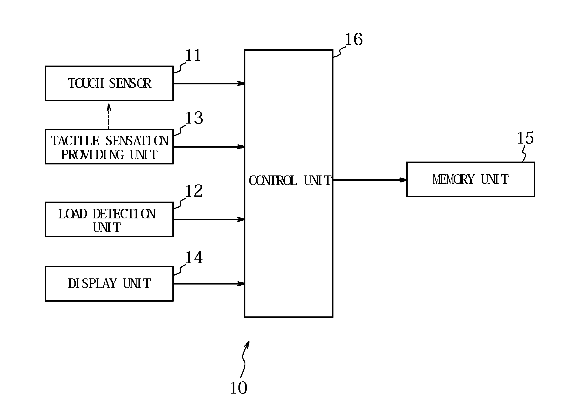
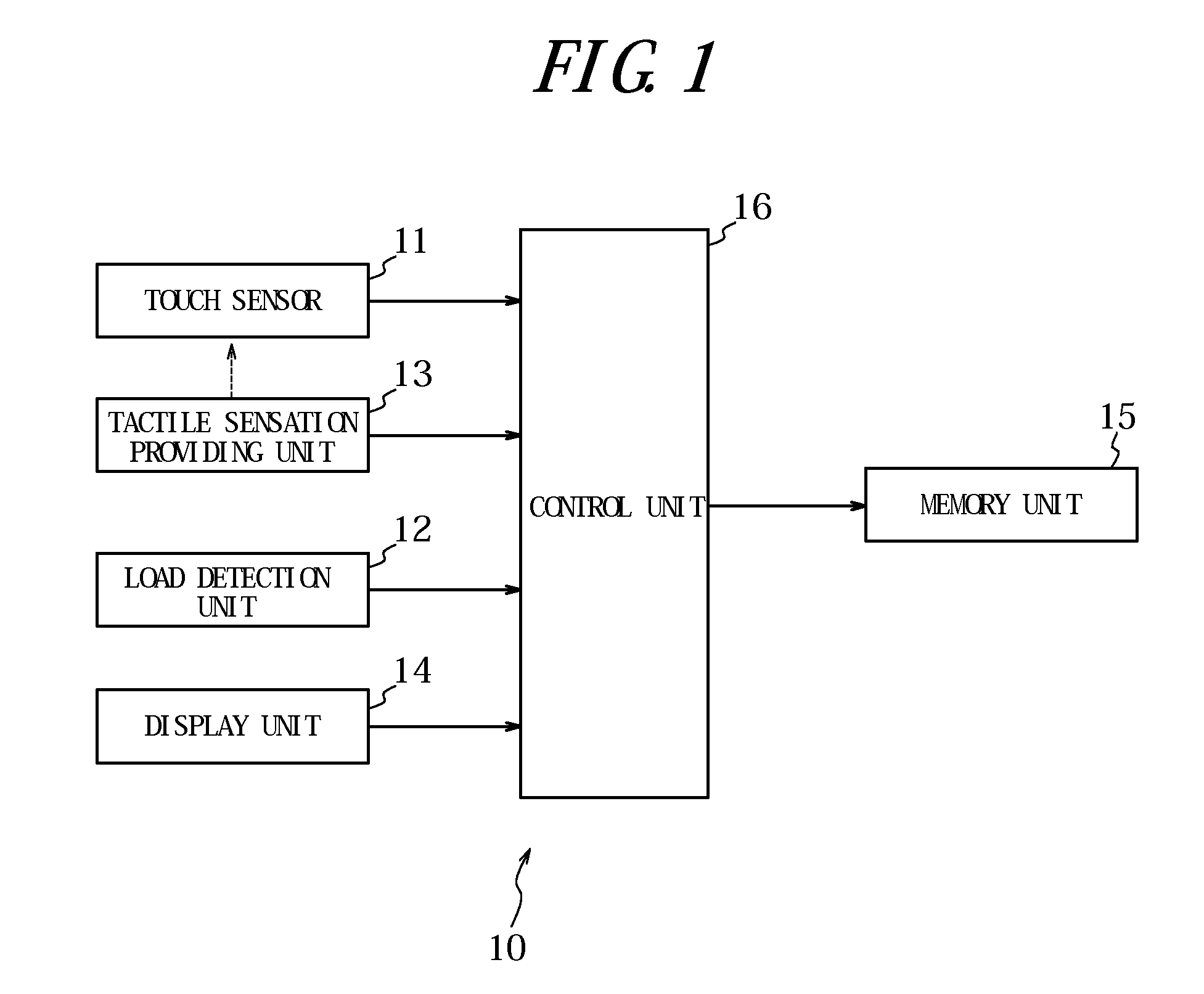
[0031]FIG. 1 is a functional block diagram schematically illustrating an internal configuration of a mobile phone 10 according to the present embodiment of the invention. As illustrated in FIG. 1, the mobile phone 10 has a touch sensor 11, a load detection unit 12, a tactile sensation providing unit 13, a display unit 14, a memory unit 15, and a control unit 16 to control overall operations.
[0032]The touch sensor 11, disposed on the display unit 14, detects a touch input to a touch face by a touch object such as a finger and the like and may be of a known type, such as a resistive film type, a capacitive type, an optical type and the like to output two-dimensional position information of a touch position. In order for the touch sensor 11 to detect the touch input, it is not necessary for the touch object to physically touch (contact) the touch sensor 11. For example, when the touch sensor 11 is of the optical type, the touch sensor 11 detects a position where an infrared ray on the ...
second embodiment
[0048]Next, processing to provide the tactile sensation of sliding and the tactile sensation of pushing according to a second embodiment of the present invention will be described.
[0049]According to the second embodiment, a condition to provide the tactile sensation of sliding and that to provide the tactile sensation of pushing to the touch object according to the first embodiment set forth above are differentiated more clearly.
[0050]FIG. 5 is a flowchart for illustrating a process to provide the tactile sensation of sliding and the tactile sensation of pushing according to the second embodiment. In the flowchart illustrated in FIG. 5, steps for the same operations as those in the flowchart in FIG. 2 according to the first embodiment are provided with the same step numbers, and descriptions thereof are omitted.
[0051]In the flowchart according to the second embodiment, the operation at each step is the same as that in the flowchart according to the first embodiment, except for shift...
third embodiment
[0055]Next, processing to provide the tactile sensation of sliding and the tactile sensation of pushing according to a third embodiment of the present invention will be described.
[0056]According to the third embodiment, a standard load for providing the tactile sensation of sliding is set lower than the standard load for providing the tactile sensation of pushing (a standard load lower than the predetermined standard load is set) according to the second embodiment set forth above.
[0057]FIG. 7 is a flowchart for illustrating a process to provide the tactile sensation of sliding and the tactile sensation of pushing according to the third embodiment. In the flowchart illustrated in FIG. 7, steps for the same operations as those in the flowchart in FIG. 5 according to the second embodiment are provided with the same step numbers, and descriptions thereof are omitted.
[0058]In the flowchart according to the third embodiment, step S301 is newly provided between step S101 and step S102 in t...
PUM
 Abstract
Description
Claims
Application Information