Lane departure warning system and method

a technology of lane departure and warning system, applied in the field of lane departure warning system and method, can solve the problems of confusion for drivers, low possibility of recognizing lane, complicated operation process, etc., and achieve the effect of high lane recognition accuracy

Inactive Publication Date: 2012-06-21
SAMSUNG ELECTRO MECHANICS CO LTD
View PDF4 Cites 34 Cited by
  • Summary
  • Abstract
  • Description
  • Claims
  • Application Information

AI Technical Summary

Benefits of technology

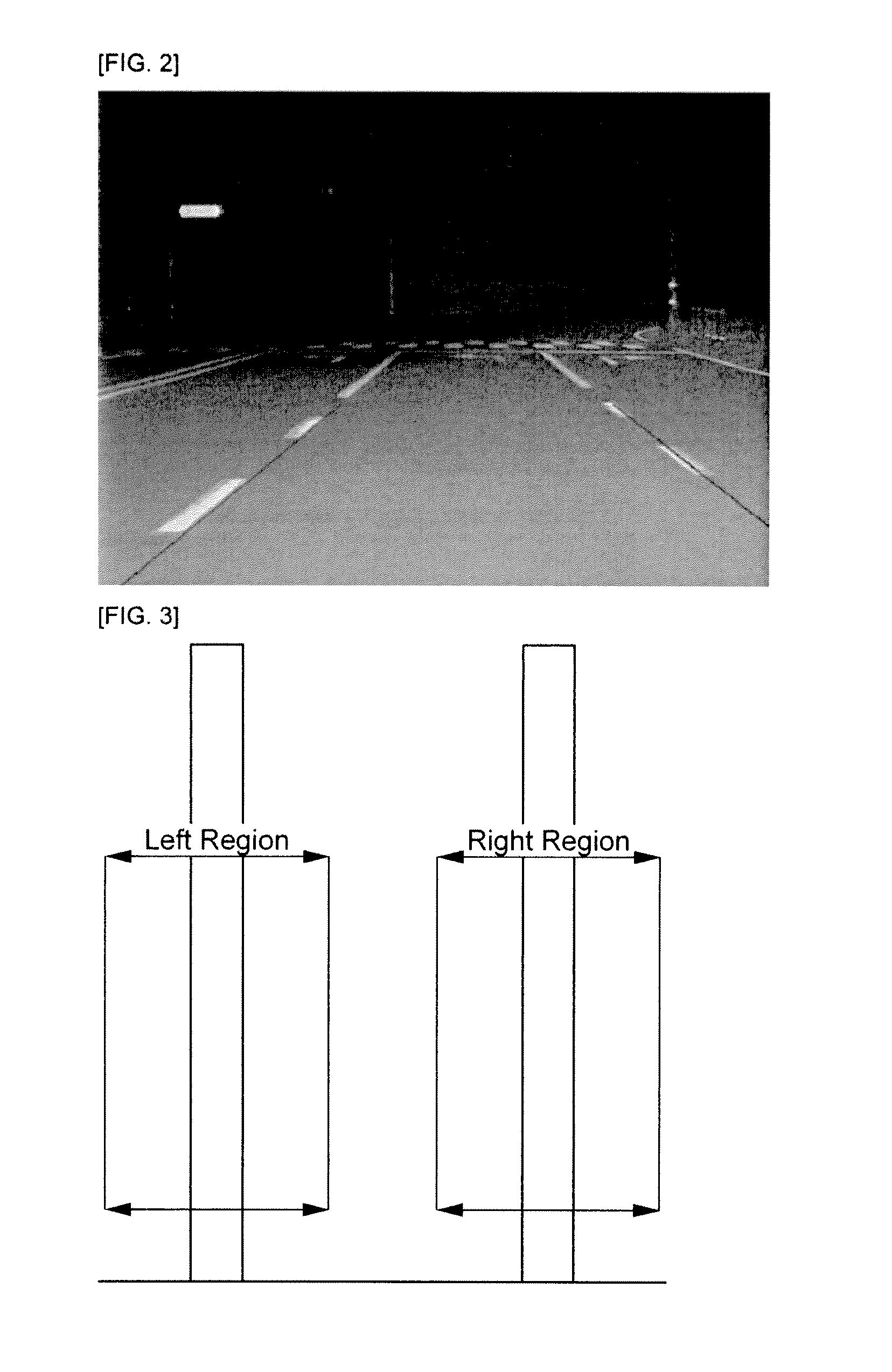
[0009]The present invention has been invented in order to overcome the above-described problems and it is, therefore, an object of the present invention to provide a lane departure warning system and method, which has high lane recognition accuracy and issues a warning to a driver even when a vehicle moves out of a solid line. The lane departure warning system includes a system configured to set a region so as to recognize a lane with respect to a region where the lane is likely to exist, and a system configured to recognize the type and color of the lane.

Problems solved by technology

However, since a typical lane departure warning system is designed to recognize a lane with respect to edge components existing in all images inputted from a camera, the possibility of recognizing a lane is low, and the operation process is complicated.
Also, a typical lane departure warning system does not distinguish between solid lines and centerlines inhibiting a lane change and dotted lines allowing a lane change, causing confusion to drivers.
Accordingly, if a turn signal lamp is determined to be on, although a vehicle approaches a solid line, the system may not recognize it as an abnormal situation.
In this case, the system does not issue any warning to a driver, which may cause a traffic accident.

Method used

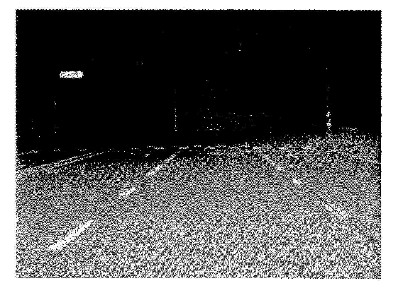

Image

  • Lane departure warning system and method
  • Lane departure warning system and method
  • Lane departure warning system and method

Examples


Embodiment Construction

[0038]Hereinafter, specific embodiments of the present invention will be described with reference to the accompanying drawings. However, the present invention is provided for the illustrative purpose only but not limited thereto.

[0039]The objects, features, and advantages of the present invention will be apparent from the following detailed description of embodiments of the invention with references to the following drawings. Descriptions of well-known components and processing techniques are omitted so as not to unnecessarily obscure the embodiments of the present invention. The following terms are defined in consideration of functions of the present invention and may be changed according to users or operator's intentions or customs. Thus, the terms shall be defined based on the contents described throughout the specification.

[0040]This invention may be embodied in different forms and should not be construed as limited to the embodiments set forth herein. Rather, these embodiments ...


PUM


Abstract

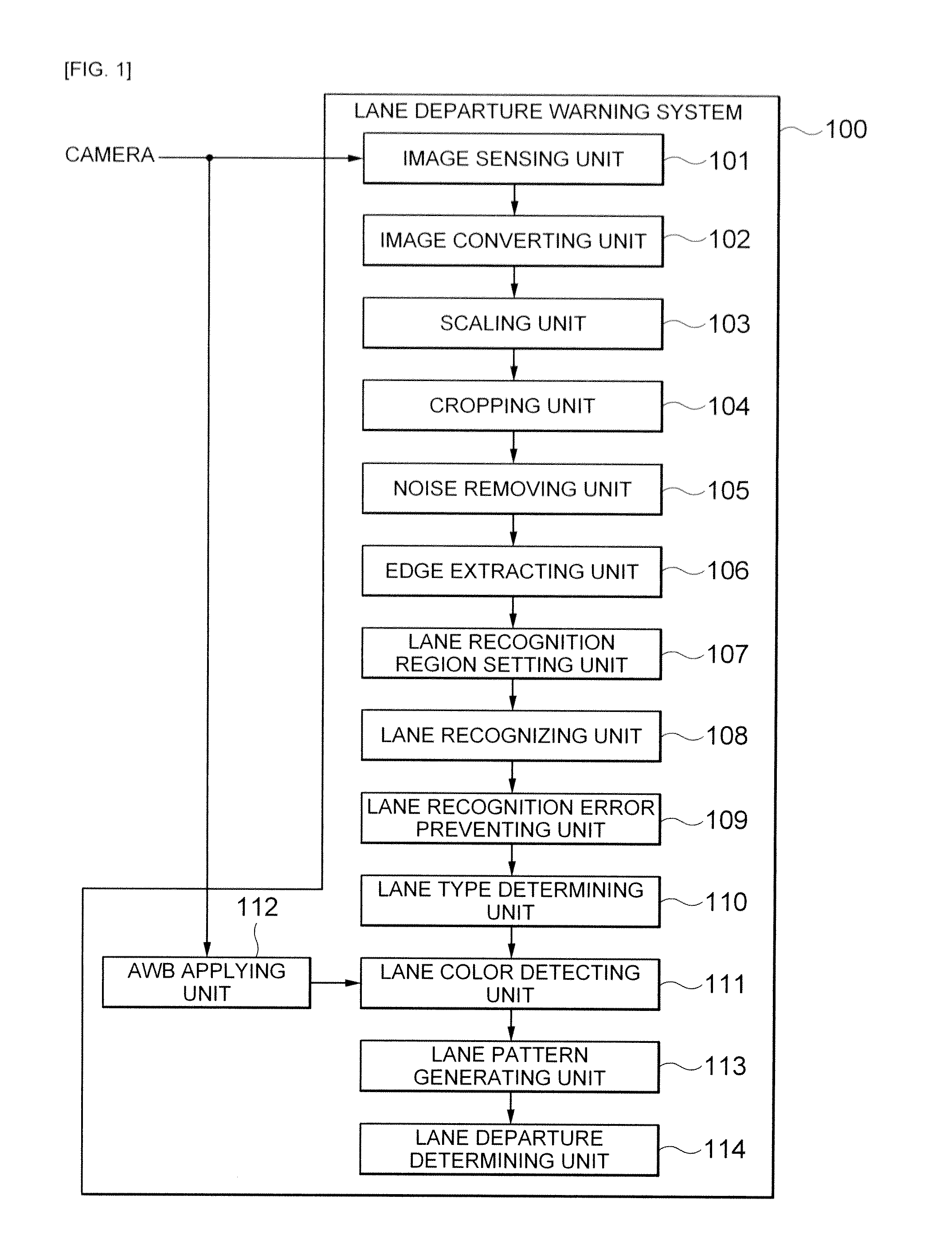
A lane departure warning system and method. The lane departure warning system includes an image sensing unit, an edge extracting unit, a lane recognizing unit, a lane type determining unit, a lane color detecting unit, a lane pattern generating unit, and a lane departure determining unit. The image sensing unit senses a plurality of images. The edge extracting unit emphasizes edge components necessary for lane recognition. The lane recognizing unit detects straight-line components. The lane type determining unit determines a type of the lane. The lane color detecting unit detects a color of the lane from an image signal value. The lane pattern generating unit generates a lane pattern. The lane departure determining unit determines lane departure in consideration of the type and the color of the lane and a state of a turn signal lamp.

Description

CROSS-REFERENCE TO RELATED APPLICATIONS[0001]This application claims the benefit of Korean Patent Application No. 10-2010-0131452 filed with the Korea Intellectual Property Office on Dec. 21, 2010 the disclosure of which is incorporated herein by reference.BACKGROUND OF THE INVENTION[0002]1. Field of the Invention[0003]The present invention relates to a lane departure warning system and method, and more particularly, to a lane departure warning system and method, which determines lane departure by recognizing the types and colors of lanes.[0004]2. Description of the Related Art[0005]Advanced Safety Vehicles (ASV) employ high electronic technology and control technology to improve safety of vehicles, increase traffic volume by reducing traffic accidents, save energy, and facilitate a driver's convenience.[0006]As an example of ASV, a Lane Departure Warning System (LDWS) is a safety apparatus that analyzes images of forward roads using cameras attached on vehicles to detect a currentl...

Claims


Application Information

Patent Timeline
Patent Type & Authority Applications(United States)
IPC IPC(8): H04N7/18G06V10/48
CPCG06K9/4633G06K9/00798G06V20/588G06V10/48
Inventor KIM, GYU WONPARK, SANG HYUNKIM, JOO HYUN
Owner SAMSUNG ELECTRO MECHANICS CO LTD
Why Eureka
Try Eureka