Stage lighting fixture

Active Publication Date: 2012-06-21
CLAY PAKY
View PDF1 Cites 6 Cited by
  • Summary
  • Abstract
  • Description
  • Claims
  • Application Information

AI Technical Summary

Benefits of technology

[0004]It is an object of the present invention to provide a stage lighting fixture designed to eliminate the above drawbacks of the known art, and which, in particular, is reliable and ensures an adequate working life of the light source.

Problems solved by technology

Stage lighting fixtures of this sortall have one drawback: frequent overheating of the light source—normally a discharge lamp—which results in impaired reliability of the fixture and obvious discomfort to the user.

Method used


Image

  • Stage lighting fixture
  • Stage lighting fixture
  • Stage lighting fixture

Examples


Embodiment Construction

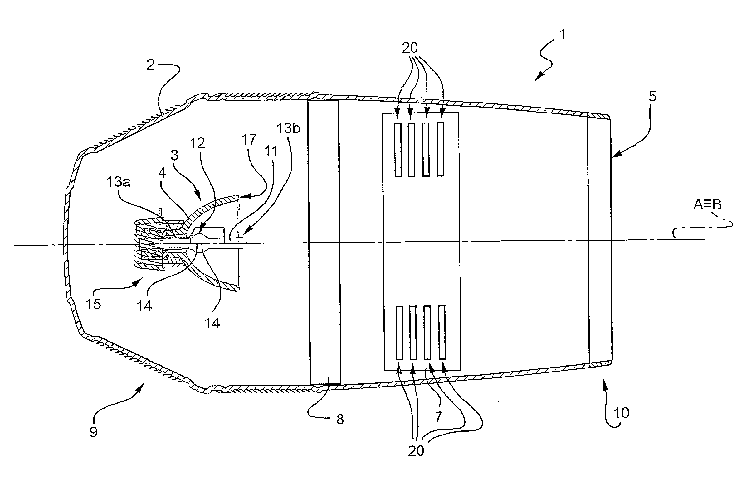
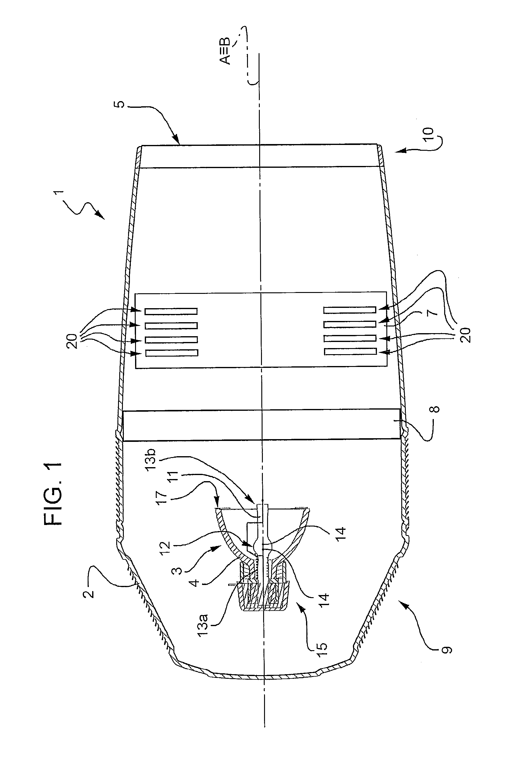
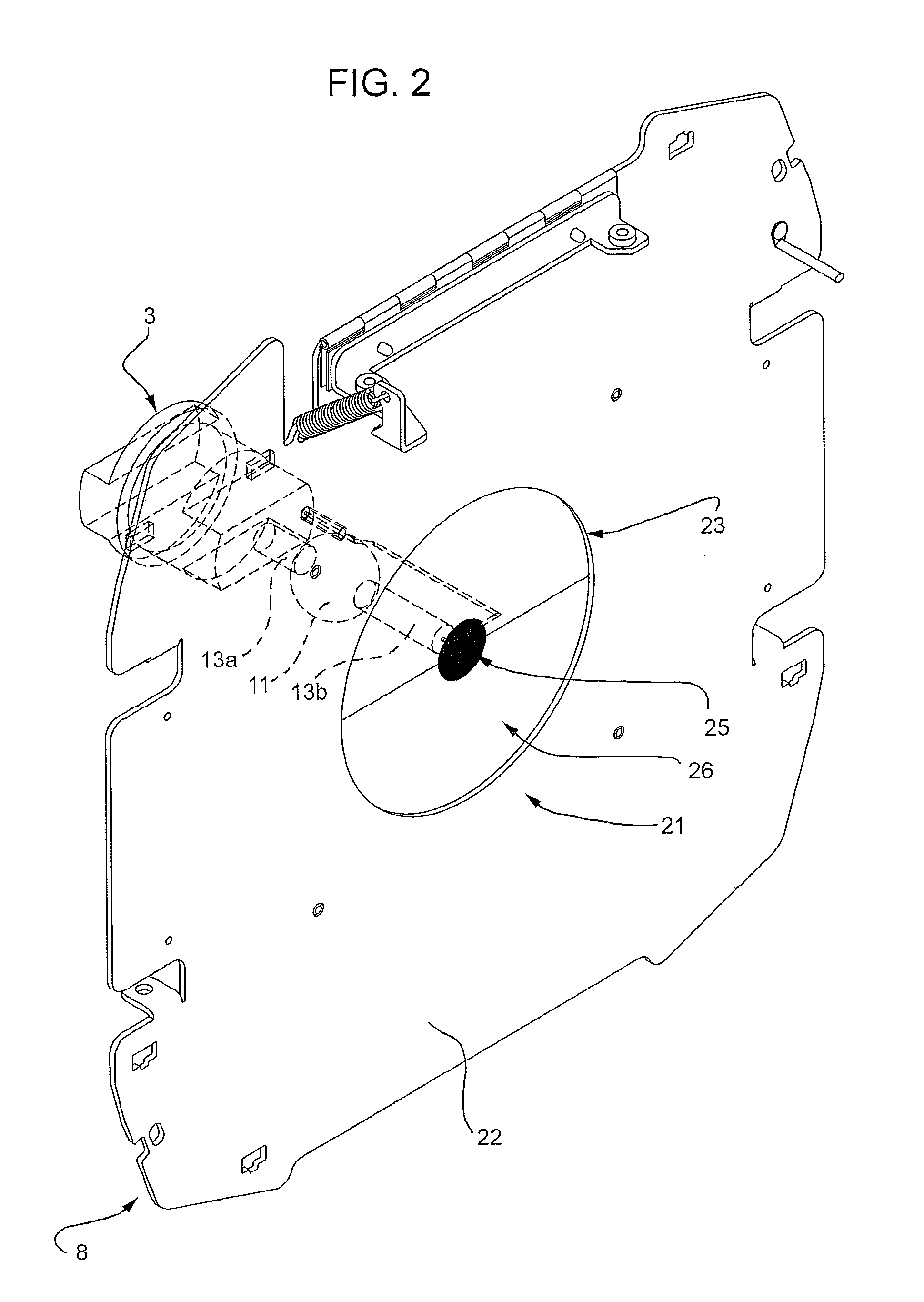
[0011]Number 1 in FIG. 1 indicates a stage lighting fixture comprising a casing 2; a light source 3; a reflector 4; an objective lens 5; a dichroic colour assembly 7 (shown schematically in FIG. 1); and a heat-shield assembly 8 (shown schematically in FIG. 1).

[0012]Casing 2 extends along a longitudinal axis A, has a closed end 9 and an open end 10 opposite closed end 9 along axis A, and is preferably supported on mounting means (not shown in the drawings for the sake of simplicity). More specifically, the mounting means and casing 2 are designed to permit rotation of casing 2 about two perpendicular, so-called PAN and TILT axes.

[0013]Light source 3 is housed inside closed end 9 of casing 2, is fitted to casing 2, and is designed to emit a light beam substantially along an optical axis B.

[0014]In the non-limiting example described and shown, optical axis B coincides with longitudinal axis A of casing 2.

[0015]Light source 3 is preferably a discharge lamp comprising a normally glass or...


PUM


Abstract

A stage lighting fixture having :a light source for emitting a light beam along an optical axis;a reflector coupled to the light source;at least one dichroic filter for selectively intercepting the light beam; andat least one heat-shield assembly located between the light source and the dichroic filter, and having a heat-shield filter, in turn having a first portion with first beam filtering properties, and a second portion with second beam filtering properties.

Description

[0001]The present invention relates to a stage lighting fixture.BACKGROUND OF THE INVENTION[0002]Stage lighting fixtures are known comprising a light source for emitting a light beam; a reflector coupled to the light source; and at least one dichroic filter for selectively intercepting and colouring the light beam.[0003]Stage lighting fixtures of this sortall have one drawback: frequent overheating of the light source—normally a discharge lamp—which results in impaired reliability of the fixture and obvious discomfort to the user.SUMMARY OF THE INVENTION[0004]It is an object of the present invention to provide a stage lighting fixture designed to eliminate the above drawbacks of the known art, and which, in particular, is reliable and ensures an adequate working life of the light source.[0005]According to the present invention, there is provided a stage lighting fixture as claimed in claim 1.BRIEF DESCRIPTION OF THE DRAWINGS[0006]A non-limiting embodiment of the present invention wi...

Claims


Application Information

Patent Timeline
IPC IPC(8): F21V13/08F21V9/40F21V29/15
CPCF21W2131/406F21V15/06F21V29/15F21V9/08F21V13/10F21V29/002F21V29/503F21V9/04F21V29/00
Inventor QUADRI, PASQUALECAVENATI, ANGELO
Owner CLAY PAKY
Why Eureka
Try Eureka