Impedance matching speaker wire system

a speaker wire and impedance matching technology, applied in the direction of loudspeakers, waveguide devices, electrical transducers, etc., can solve the problems of power supply failure, poor transducer response, and load may be underutilized

Active Publication Date: 2012-06-21
CRESTRON ELECTRONICS
View PDF6 Cites 5 Cited by
  • Summary
  • Abstract
  • Description
  • Claims
  • Application Information

AI Technical Summary

Problems solved by technology

If the impedance of the load is greater than the impedance of the source, the load may be underutilized.
Alternatively, if the impedance of the load is sufficiently less than the impedance of the source, the current draw by the load increases and may cause the power supply to fail.
If the impedances are mismatched, unwanted resonances may occur and may result in a much flatter response by the transducer.

Method used


Image

  • Impedance matching speaker wire system
  • Impedance matching speaker wire system
  • Impedance matching speaker wire system

Examples


Embodiment Construction

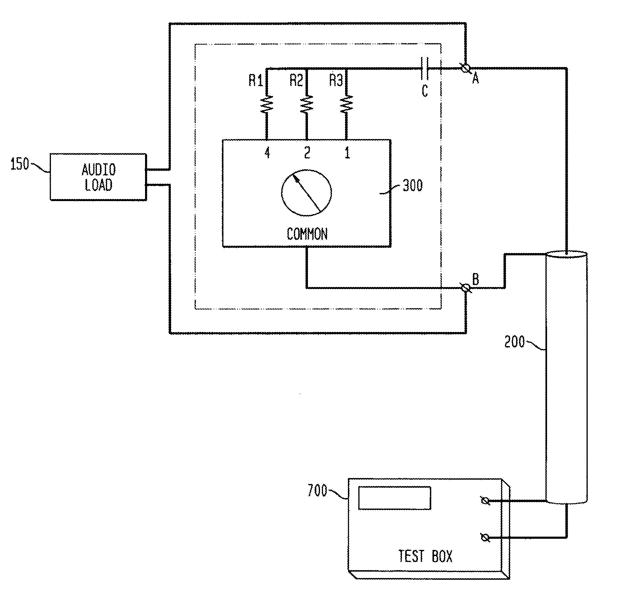
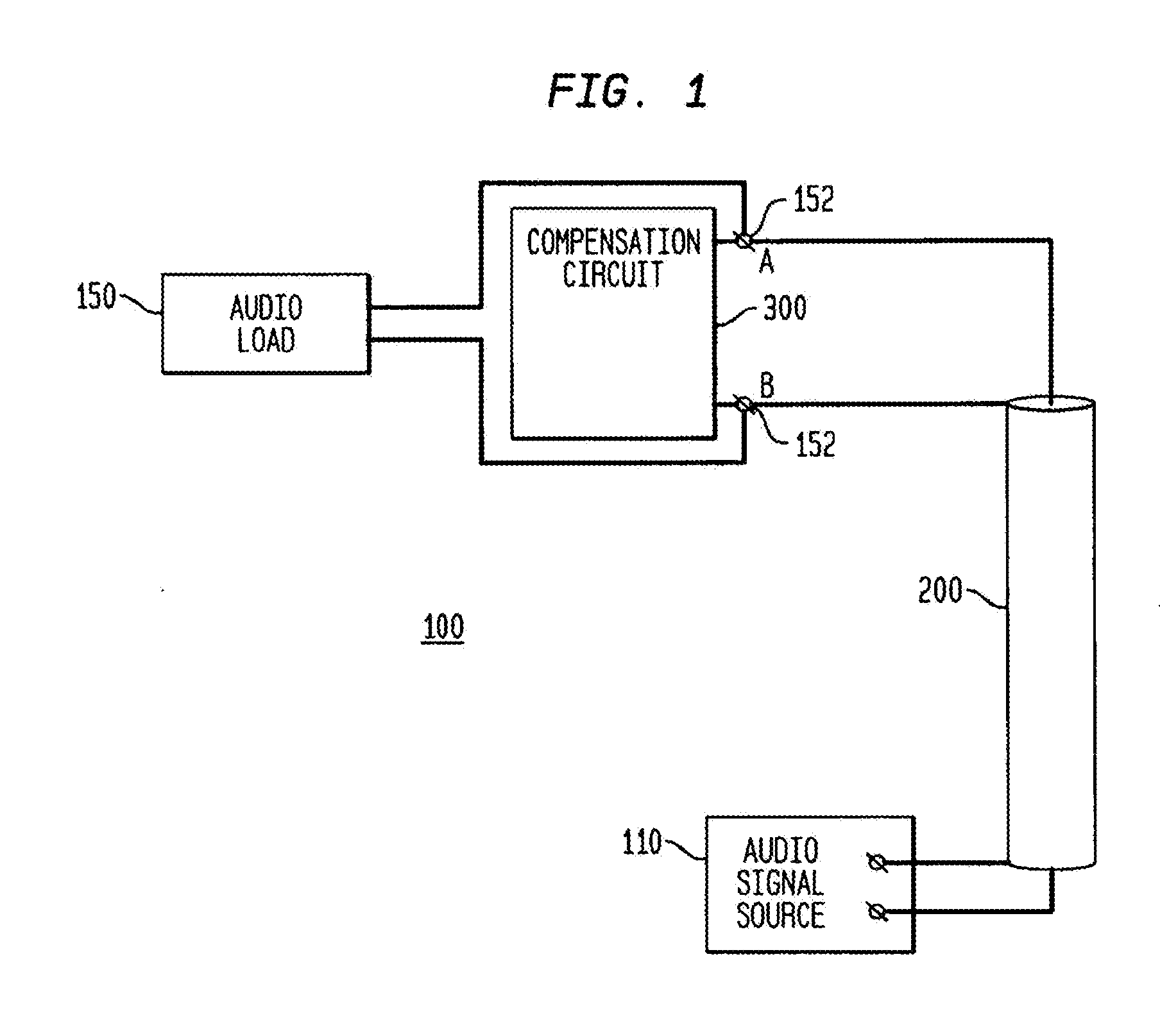
[0029]FIG. 1 schematically illustrates an audio transmission system 100 according to an embodiment of the invention. The audio transmission system 100 includes an audio signal source 110 which includes a class D audio amplifier and which delivers power to a speaker or other audio load 150. Alternatively, or additionally, the audio load may be a recorder. A coaxial line 200 is connected at one end to the output of the audio signal source 110 using, for example, compression ferrules (not shown). At the other end of the coaxial line, a compensation circuit 300 is connected, such as also using compression ferrules. The compensation circuit is connected across the input terminals 152 of the audio load 150.

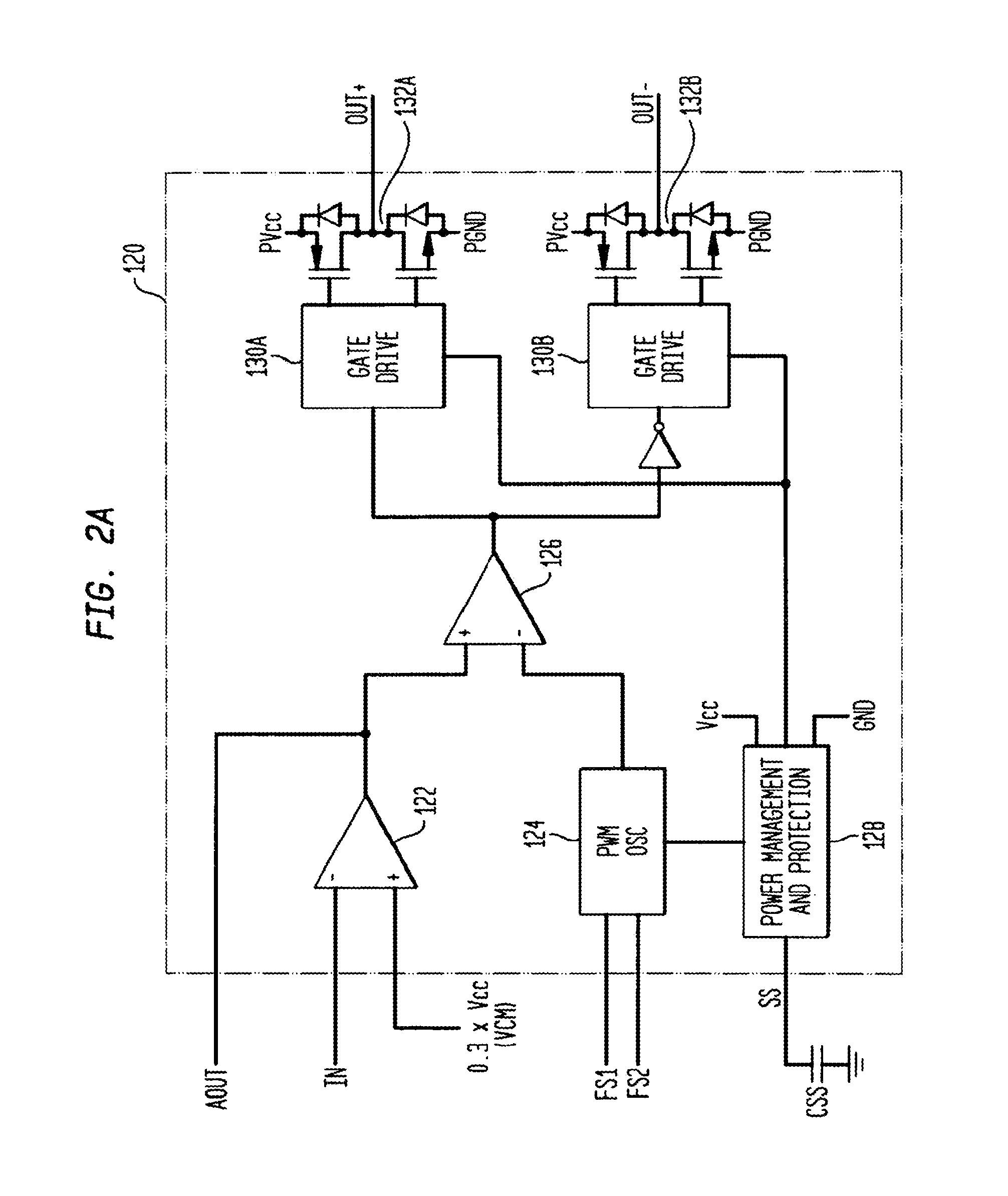
[0030]FIG. 2A schematically illustrates an example of a class D audio amplifier 120. Such class D audio amplifiers are known in the art and may include, e.g., one or more input preamplifiers 122, a sawtooth wave oscillator 124, one or more comparators 126, one or more MOSFET drivers 130...


PUM


Abstract

An impedance matched connection is provided between a load and a power source that outputs signals within a predetermined frequency range. A coaxial line has a predetermined characteristic impedance, an inner conductor, an outer conductor, and an insulator between the conductors. Each conductor has a first end electrically connectable to output terminals of the power source. A compensation circuit has an adjustable impedance, a first terminal electrically connected to a second end of the inner conductor and to a first terminal of the load, and a second terminal electrically connected to a second end of the outer conductor and to a second terminal of the load. The compensation circuit is adjustable to attain, for a pulse having a rise time / fall time faster than the rise / fall times associated with the predetermined range of frequencies, a combined impedance and load that is substantially equal to the characteristic impedance of the coaxial line.

Description

BACKGROUND OF THE INVENTION[0001]1. Technical Field[0002]The present invention is directed to cabling and transmission lines and, in particular, to a coaxial cable arrangement and a compensation circuit for matching impedances, such as for a speaker wire system used for audio applications.[0003]2. Background Art[0004]When a source of power, such as an audio signal source, etc., feeds a resistive load, the maximum available power is delivered to the load when the impedance of the load matches the impedance of the source. If the impedance of the load is greater than the impedance of the source, the load may be underutilized. Alternatively, if the impedance of the load is sufficiently less than the impedance of the source, the current draw by the load increases and may cause the power supply to fail. Moreover, if the impedance of the load does not match the impedance of the source, some of the power generated by the source is not transferred to the load but is instead reflected back to...

Claims


Application Information

Patent Timeline
Patent Type & Authority Applications(United States)
IPC IPC(8): H03F99/00H03H7/38
CPCH04R3/00H04R2400/00
Inventor FELDSTEIN, GEORGEDRAGANOVIC, KRUNOSLAV ESTEBAN
Owner CRESTRON ELECTRONICS
Why Eureka
Try Eureka