
Apparatus for cooking by heat convection comprising temperature control layer

Inactive Publication Date: 2012-06-28
KO YOUNG SHIN
View PDF13 Cites 0 Cited by
  • Summary
  • Abstract
  • Description
  • Claims
  • Application Information

AI Technical Summary

Benefits of technology

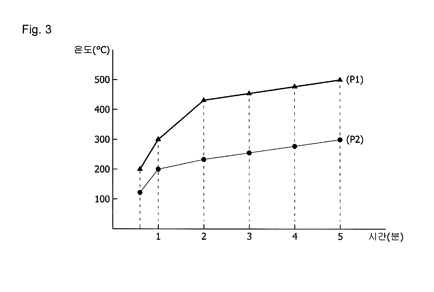
[0019]According to the embodiments of the present invention, the cooker is gradually heated up with a maximum temperature kept constant at 350 due to the temperature control layer. Accordingly, food is prevented from burning soon.

Problems solved by technology

Conventional cookware, when heated for cooking, transfers the majority of heat to food therein because it has high thermal conductivity, thus causing the food to burn soon.

Method used


Image

  • Apparatus for cooking by heat convection comprising temperature control layer
  • Apparatus for cooking by heat convection comprising temperature control layer
  • Apparatus for cooking by heat convection comprising temperature control layer

Examples


Embodiment Construction

[0024]Hereinafter, embodiments of the present invention will be described in detail with reference to the accompanying drawings, wherein the same reference numerals may be used to denote the same or substantially the same elements throughout the specification and the drawings.

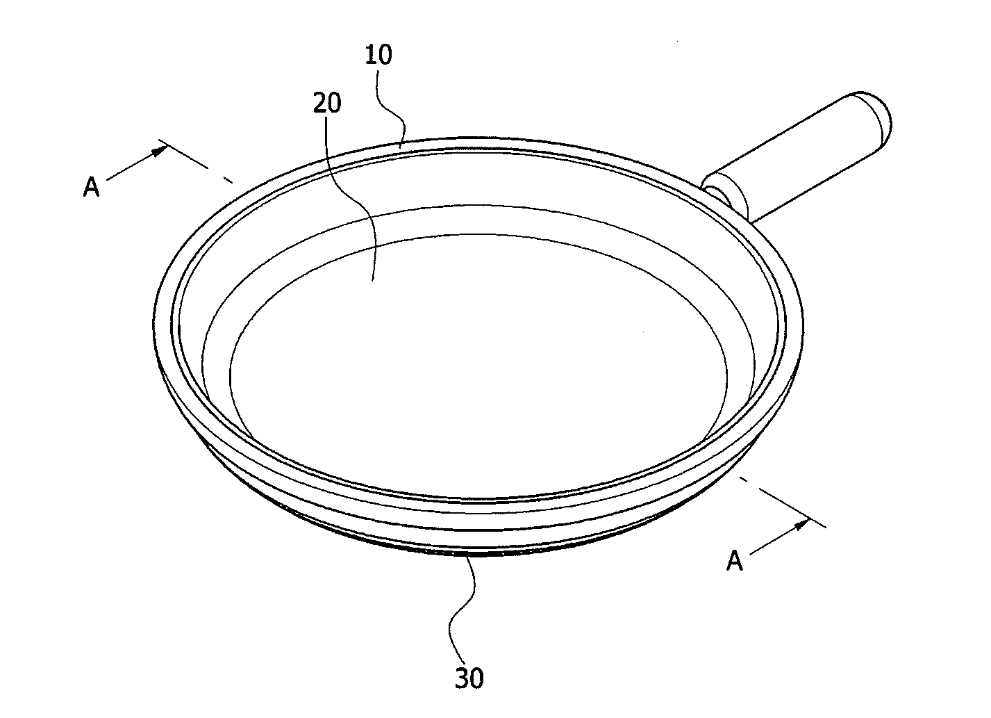
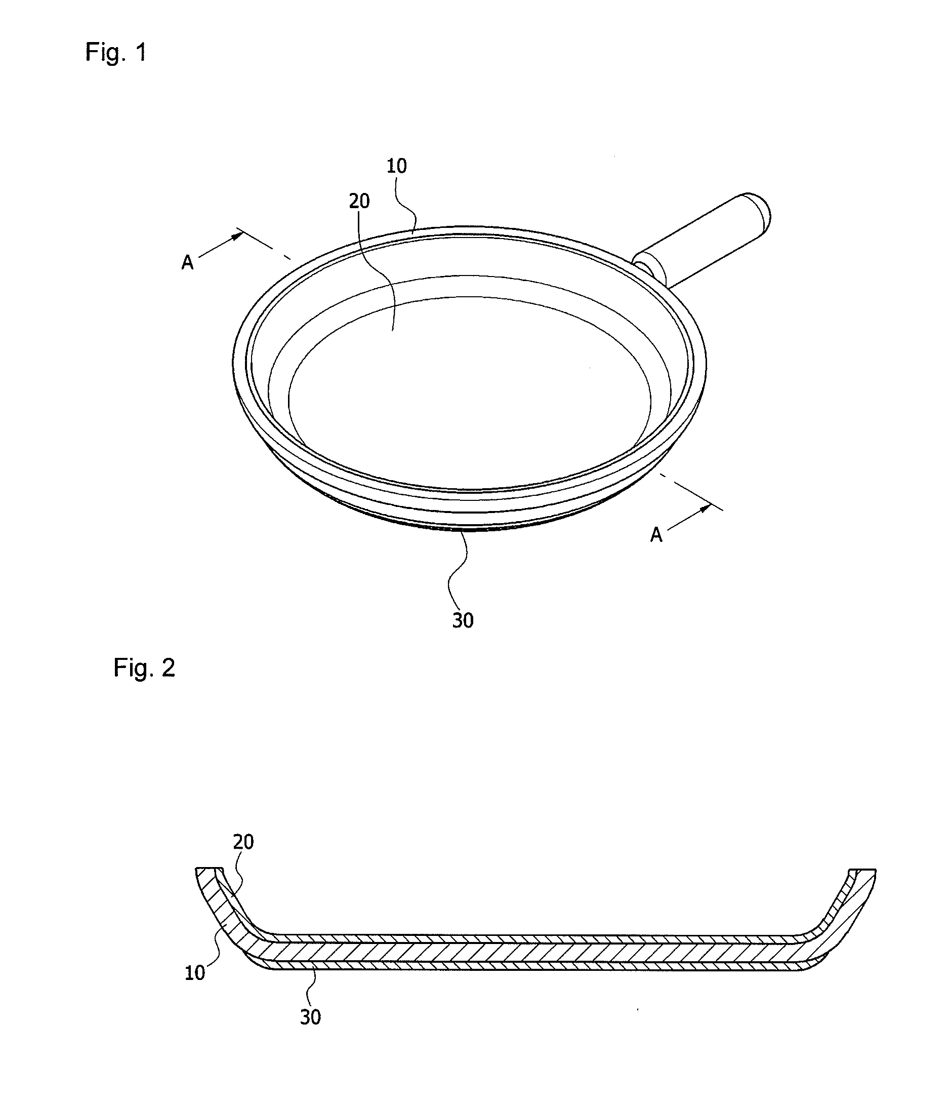
[0025]Referring to FIG. 1, a cooker according to an embodiment includes a heating part 10 and a handle. The heating part 10 contacts heat. The heating part 10 includes an outer surface and an inner surface. The outer surface directly receives heat. The inner surface is opposite to the outer surface. An object to be cooked is seated on the inner surface to be indirectly heated via the outer and inner surfaces.

[0026]The cooker is not limited to a specific type. Any type of cooker may be included in the cooker as long as the outer surface is directly heated while food may be cooked on the inner surface. Examples of the cooker include a one-sided or both-sided frying pan, a pan for barbecue or flour mixtures, grill...


PUM


Abstract

A cooker and a method of manufacturing the cooker are provided. The cooker includes a heating part contacting heat, and a temperature control layer on a first surface of the heating part, wherein the temperature control layer includes expandable graphite.

Description

CROSS-REFERENCE TO RELATED APPLICATION[0001]This application claims priority to Korean Patent Application No. 10-2010-0134648 filed on Dec. 24, 2010, the contents of which are herein incorporated by reference in its entirety.BACKGROUND[0002]1. Technical Field[0003]The embodiments of the present invention are directed to a cooker, and more specifically to a cooker having a temperature control layer that inhibits the cooker from being excessively heated up, thus preventing food from burning.[0004]2. Discussion of the Related Art[0005]Conventional cookware, when heated for cooking, transfers the majority of heat to food therein because it has high thermal conductivity, thus causing the food to burn soon. Accordingly, there is a need for a cooker that may prevent a sharp increase in temperature and may maintain a constant maximum temperature even though being kept heated, thereby preventing food from burning.SUMMARY[0006]According to an embodiment of the present invention, there is prov...

Claims


Application Information

Patent Timeline
IPC IPC(8): A47J37/10B05D5/00B05D7/22
CPCA47J36/04C01B33/32C01B33/26
Inventor KO, YOUNG SHIN
Owner KO YOUNG SHIN
Learn More