Vehicle brake system

a brake system and vehicle technology, applied in the direction of brake action initiation, vehicle components, braking systems, etc., can solve the problems of inability to respond to solenoid valves, inability to create problems, and inability to impact noise, so as to achieve high responsiveness and minimize noise.

Active Publication Date: 2012-06-28
HONDA MOTOR CO LTD
View PDF11 Cites 25 Cited by
  • Summary
  • Abstract
  • Description
  • Claims
  • Application Information

AI Technical Summary

Benefits of technology

The objective of this patent is to create a brakes for vehicles that have minimal noise from the pneumatic parts used in conventional systems. This will make them more effective and efficient.

Problems solved by technology

The technical problem addressed in this patent relates to improving the performance of brakes used in electric or hybrid vehicles during regenerative braking without compromising their responsiveness. Specifically, the issue involves minimizing the noise generated due to the operation of a solenoid valve located between the master cylinder and the wheels, which can cause issues like rattling or tapping sounds.

Method used


Image

  • Vehicle brake system
  • Vehicle brake system
  • Vehicle brake system

Examples


Embodiment Construction

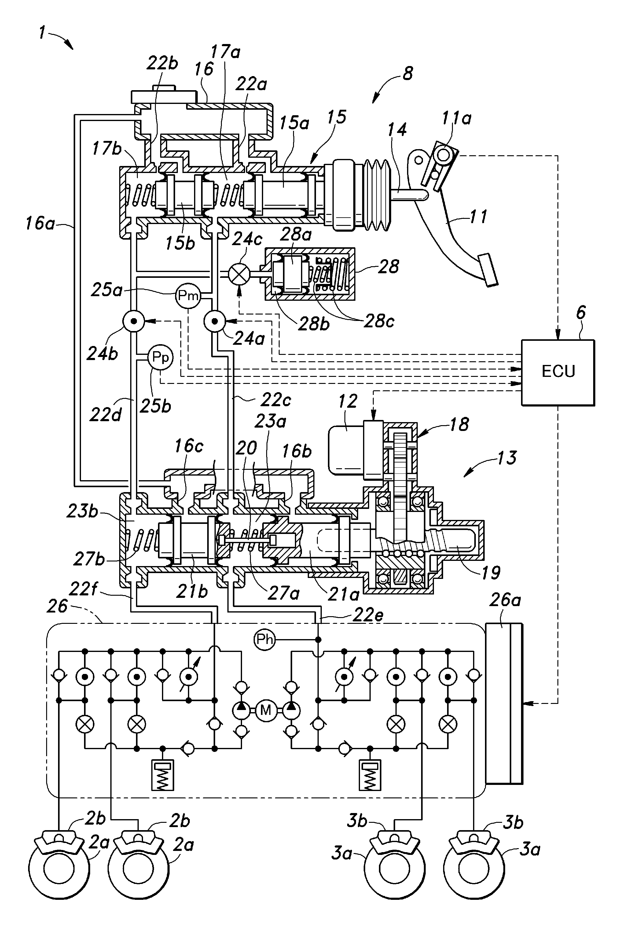
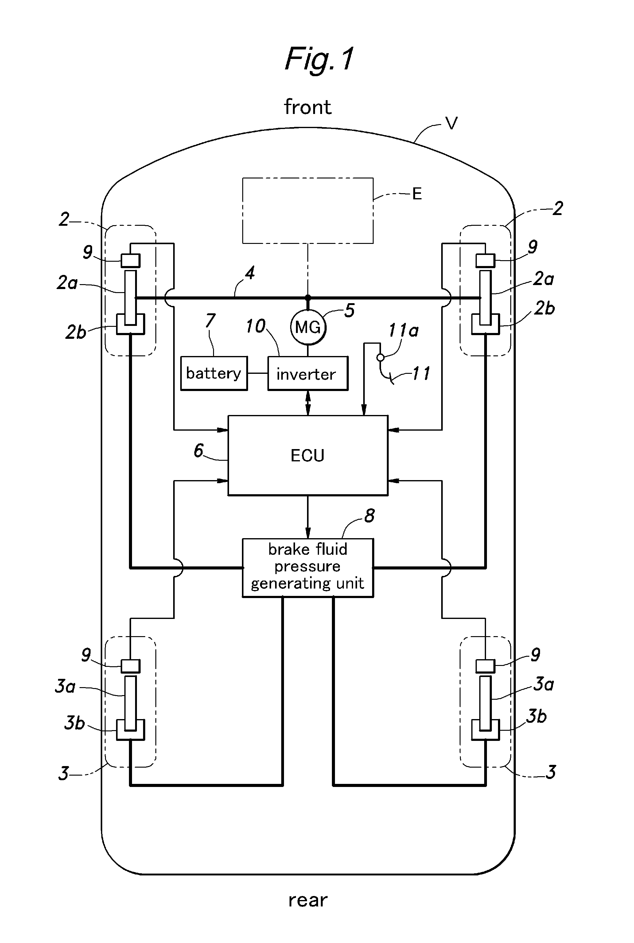
[0022]FIG. 1 shows a brake system of an electric or hybrid vehicle embodying the present invention. This vehicle V comprises a pair of front wheels 2 located on the front side thereof and a pair of rear wheels 3 located on the rear side thereof. The front wheels 2 are connected to front axles 4 which are in turn connected to a motor / generator 5 in a torque transmitting relationship via a differential gear device (not shown in the drawing).

[0023]The motor / generator 5 operates both as an electric motor for propelling the vehicle and a generator for providing a regenerative braking. More specifically, the motor / generator 5 can receive electric power from a rechargeable battery 7 serving as a power source via an inverter 10, and can also supply electric power to (recharge) the battery 7 by converting the kinetic energy into electric power by the regenerative braking.

[0024]A control unit (ECU) 6 incorporated with a CPU control circuit performs various control actions for the vehicle V in...


PUM


Abstract

In a brake-by-wire vehicle brake system that uses a solenoid shut-off valve (24a, 24b), the electric power supplied to the solenoid (33) of the solenoid shut-off valve is controlled so as to decelerate a movement of a plunger (31, 32) of the valve as the plunger reaches a point immediately adjacent to a terminal point thereof. Thereby, a highly responsive property can be achieved while the noises that are generated by the plunger striking a stopper (36) or a valve seat (34) can be minimized. When actuating the plunger in the valve closing direction, the solenoid may receive electric power at a first level, a second level lower than the first level and a third level intermediate between the first and second levels in that order.

Description


Claims


Application Information

Patent Timeline
Owner HONDA MOTOR CO LTD
Why Eureka
Try Eureka