
Cognitive radio cooperative spectrum sensing method and fusion center performing cognitive radio cooperative spectrum sensing

a cognitive radio and cooperative spectrum technology, applied in the field of radio communication, can solve problems such as the inability of the user to accurately detect a vacant frequency band

Inactive Publication Date: 2012-06-28
POSTECH ACAD IND FOUND
View PDF3 Cites 27 Cited by
  • Summary
  • Abstract
  • Description
  • Claims
  • Application Information

AI Technical Summary

Benefits of technology

[0021]Calculating the optimum number of SUs may include: calculating a number {tilde over (K)} minimizing an overall detection error probability using the following equation:K~=ln(P(H1)PmNP(H0)(1-Pf)N)ln(Pf·Pm(1-Pf)(1-Pm))
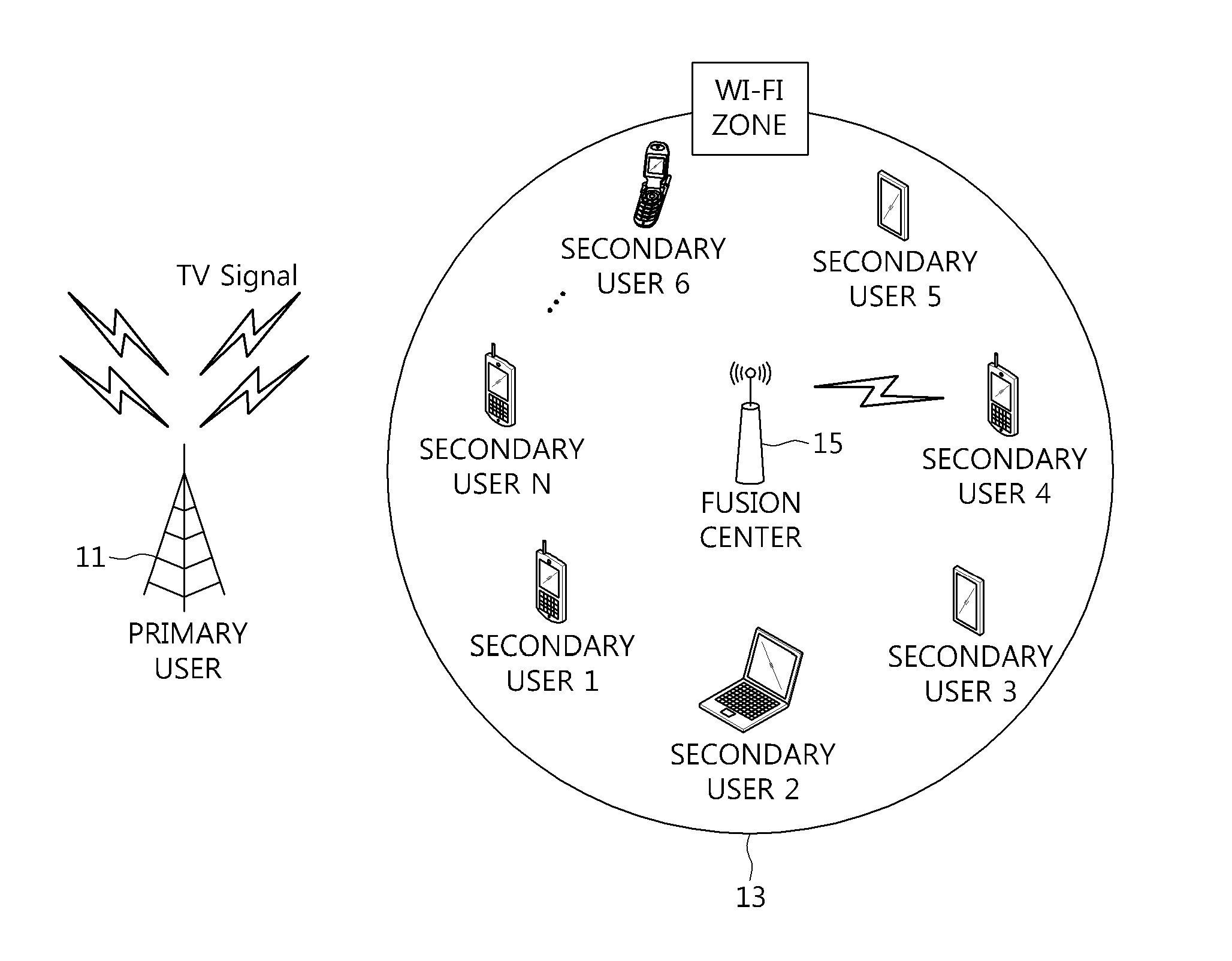
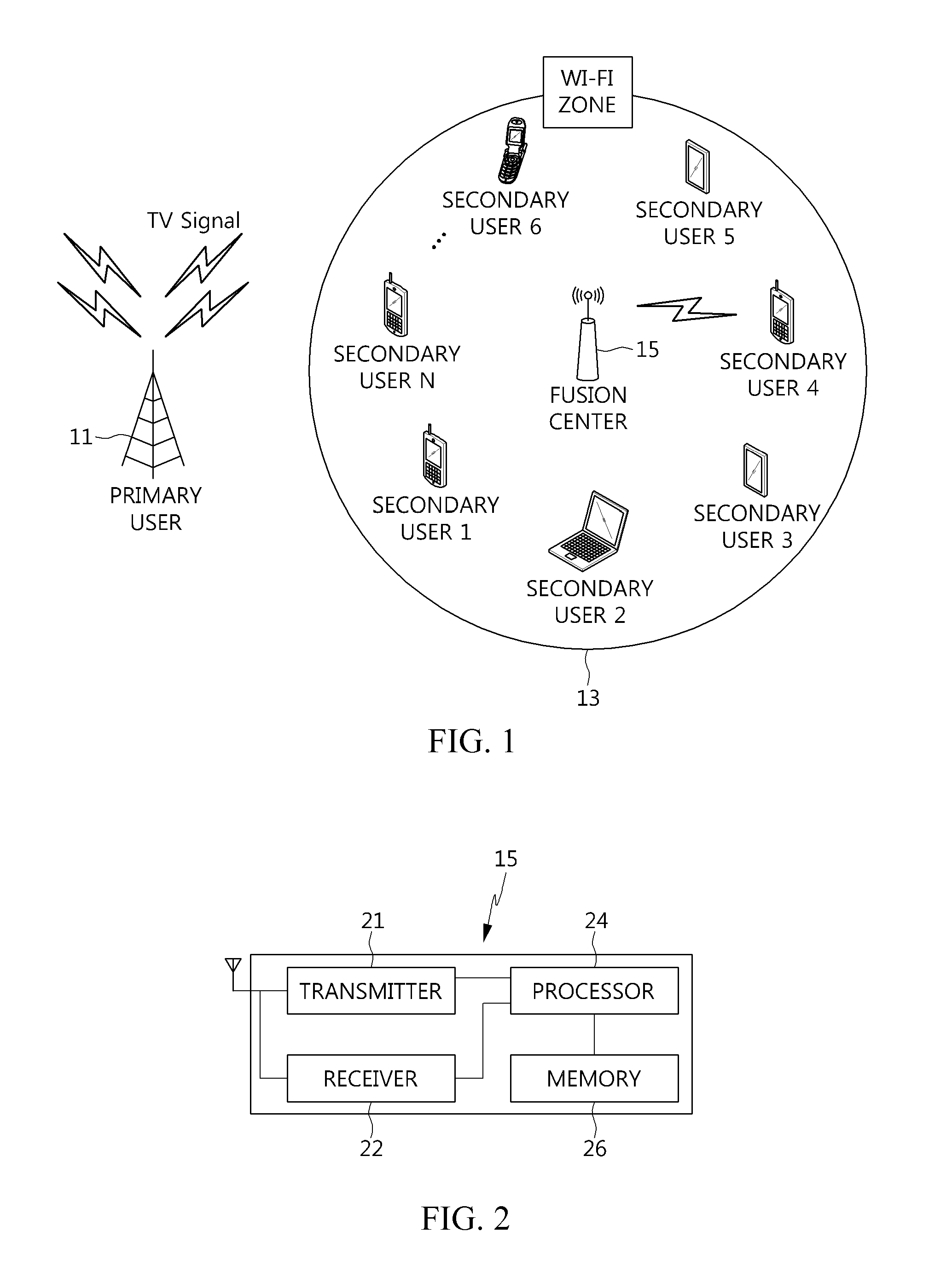
[0027]The SU number determiner may calculate a number {tilde over (K)} minimizing an overall detection error probability using the following equation:K~=ln(P(H1)PmNP(H0)(1-Pf)N)ln(Pf·Pm(1-Pf)(1-Pm)),and determine a natural number closest to {tilde over (K)} as the optimum number of SUs. Here, P(H1) is a probability that the PU will be using the predetermined frequency band, P(H0) is a probability that the PU will not be using the predetermined frequency band, Pm is a miss-detection probability of an SU (probability that the SU cannot detect a signal transmitted from the PU), Pf is a false alarm probability of the SU, and N is the number of SUs in the predetermined zone.

Problems solved by technology

However, when one SU separately performs spectrum sensing, the SU may not accurately detect a vacant frequency band because of hidden nodes, shadow fading, multipath fading, etc.

Method used


Image

  • Cognitive radio cooperative spectrum sensing method and fusion center performing cognitive radio cooperative spectrum sensing
  • Cognitive radio cooperative spectrum sensing method and fusion center performing cognitive radio cooperative spectrum sensing
  • Cognitive radio cooperative spectrum sensing method and fusion center performing cognitive radio cooperative spectrum sensing

Examples


Embodiment Construction

[0034]Example embodiments of the present invention are disclosed herein. However, specific structural and functional details disclosed herein are merely representative for purposes of describing example embodiments of the present invention. Example embodiments of the present invention may be embodied in many alternate forms and should not be construed as limited to example embodiments of the present invention set forth herein.

[0035]Accordingly, while the invention is susceptible to various modifications and alterations in form, specific embodiments thereof are shown by way of example in the drawings and will herein be described in detail. It should be understood, however, that there is no intent to limit the invention to the particular forms disclosed. On the contrary, the invention is to cover all modifications, equivalents, and alternatives falling within the spirit and scope of the invention. Like numbers refer to like elements throughout the description and the figures.

[0036]It ...


PUM


Abstract

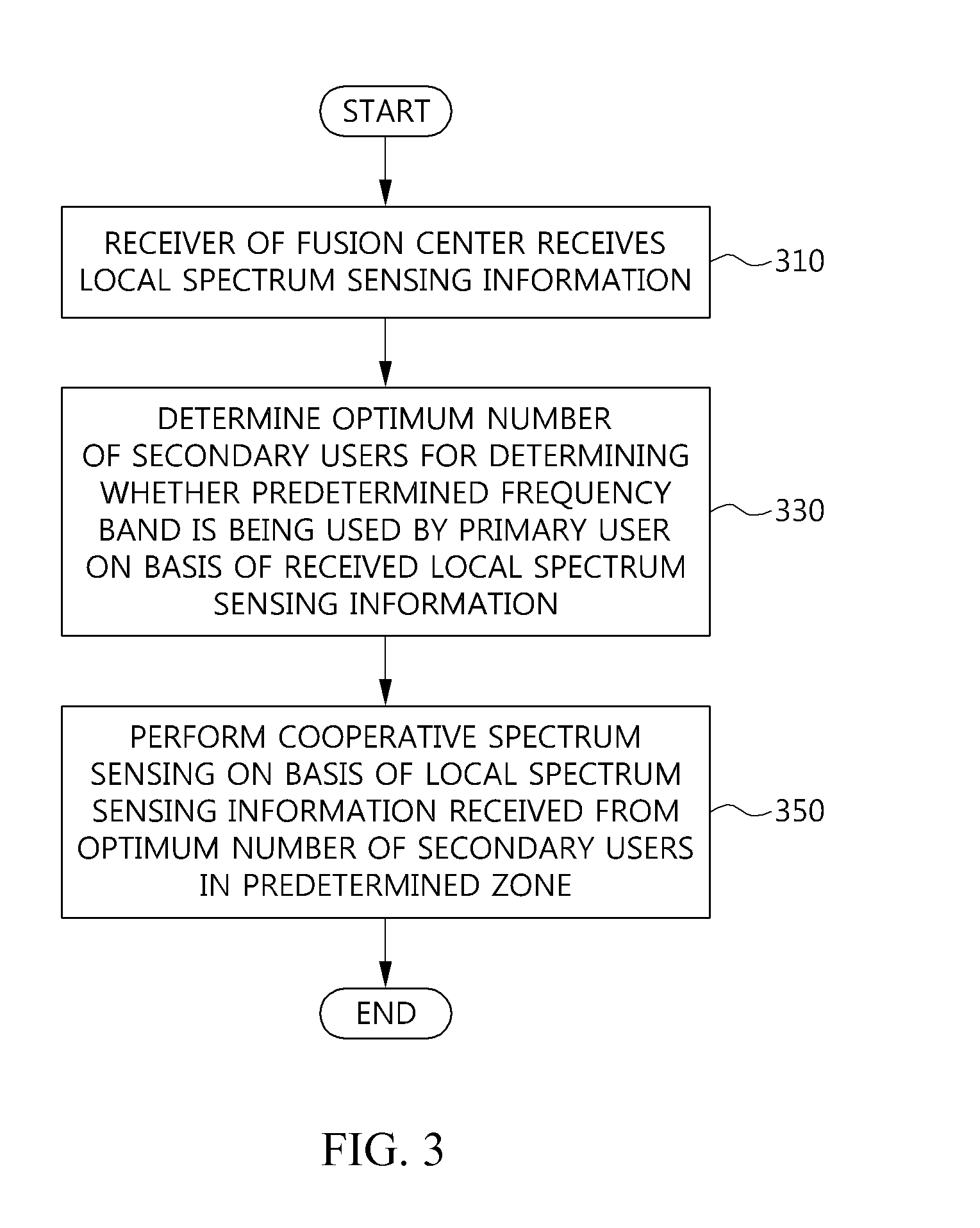
Provided are a cognitive radio (CR) cooperative spectrum sensing method and a fusion center (FC) performing CR cooperative spectrum sensing. The CR cooperative spectrum sensing method includes receiving, at an FC, local spectrum sensing information about a predetermined frequency band from each of N secondary users (SUs) in a predetermined zone, determining, at the FC, the optimum number of SUs for determining whether the predetermined frequency band is being used by a primary user (PU) on the basis of the received local spectrum sensing information, and performing cooperative spectrum sensing on the basis of local spectrum sensing information received from the optimum number of SUs in the predetermined zone. The method is implemented by the FC. Accordingly, the method and FC find how many SUs are needed to determine that a frequency of a PU is being used in a corresponding-channel situation, thereby enabling efficient communication.

Description

CLAIM FOR PRIORITY[0001]This application claims priority to Korean Patent Application No. 10-2010-0136851 filed on Dec. 28, 2010 in the Korean Intellectual Property Office (KIPO), the entire contents of which are hereby incorporated by reference.BACKGROUND OF INVENTION[0002]1. Technical Field[0003]Example embodiments of the present invention relate to a national research and development project having subject No. ITAC1090103100090001000100100, project name “University IT Research Center Promotion and Support Project,” and subject title “Research on Embedded Software Technology for Convergence Terminal.”[0004]Example embodiments of the present invention relate in general to radio communication, and more specifically, to a cognitive radio (CR) cooperative spectrum sensing method and a fusion center (FC) performing CR cooperative spectrum sensing.[0005]2. Related Art[0006]Currently, radio communication technology is being researched and developed for a ubiquitous network in which any i...

Claims


Application Information

Patent Timeline
Patent Type & Authority Applications(United States)
IPC IPC(8): H04W24/00H04W84/02
CPCH04W84/18H04W16/14H04L27/0006
Inventor HEO, JUNYOU, CHONG JOONLEE, JAE YOUNG
Owner POSTECH ACAD IND FOUND
Learn More