Wireless power transmission audio system and device on transmitting end and loudspeaker for use in such a system

a technology of power transmission audio and loudspeaker, which is applied in the direction of electrical transducers, digital transmission, near-field systems using receivers, etc., can solve the problems of difficult to set the distance between the transmitting and receiving coils b>911/b> and b>912/b> to be long enough, and achieve the same transfer efficiency and improve the performance of the wireless power transmission unit for the loudspeaker

Inactive Publication Date: 2012-06-28
PANASONIC INTELLECTUAL PROPERTY MANAGEMENT CO LTD
View PDF2 Cites 29 Cited by
  • Summary
  • Abstract
  • Description
  • Claims
  • Application Information

AI Technical Summary

Benefits of technology

[0033]According to the present invention, if the impedance is changed in order to maintain the same transfer efficiency even when the distance between the audio device (an exemplary device on the transmitting end) itself and the loudspeaker changes, the waveform of the transmission signal (e.g., as for a pulse-width-modulated (PWM modulated) transmission signal, the amplitude and pulse width of the PWM modulated pulses) is changed. In this manner, it is possible to avoid an unwanted situation where the volume changes discontinuously before and after the impedance is changed. As a result, the performance of a wireless power transmission unit for a loudspeaker can be improved.

Problems solved by technology

However, when electric power and an audio signal are transmitted wirelessly to a loudspeaker, the distance from the audio device to the loudspeaker is not always constant but the position of the loudspeaker may need to be changed arbitrarily in some system.
If such a wireless power transmission method by electromagnetic induction is adopted, it is difficult to set the distance between the transmitting and receiving coils 911 and 912 to be long enough.
This is because according to the electromagnetic induction method, the longer the coil-to-coil distance, the more significantly the power transfer efficiency would decrease.
For that reason, such a wireless power transmission system is supposed to be used with the coils always arranged close to each other, and therefore, is hard to cope with a situation where the coil-to-coil distance varies.
Nevertheless, a circuit for changing the impedance continuously usually has a large circuit size and requires a complicated control.
In transmitting electric power and an audio signal at the same time by the magnetic resonance method, however, if the distance between the audio device itself and the loudspeaker changes, the audio signal could not be obtained as intended.
The present inventors confirmed via experiments that particularly when the transfer efficiency was increased by controlling the impedances as described above, the audio signal thus obtained often had problems.

Method used


Image

  • Wireless power transmission audio system and device on transmitting end and loudspeaker for use in such a system
  • Wireless power transmission audio system and device on transmitting end and loudspeaker for use in such a system
  • Wireless power transmission audio system and device on transmitting end and loudspeaker for use in such a system

Examples


embodiment 1

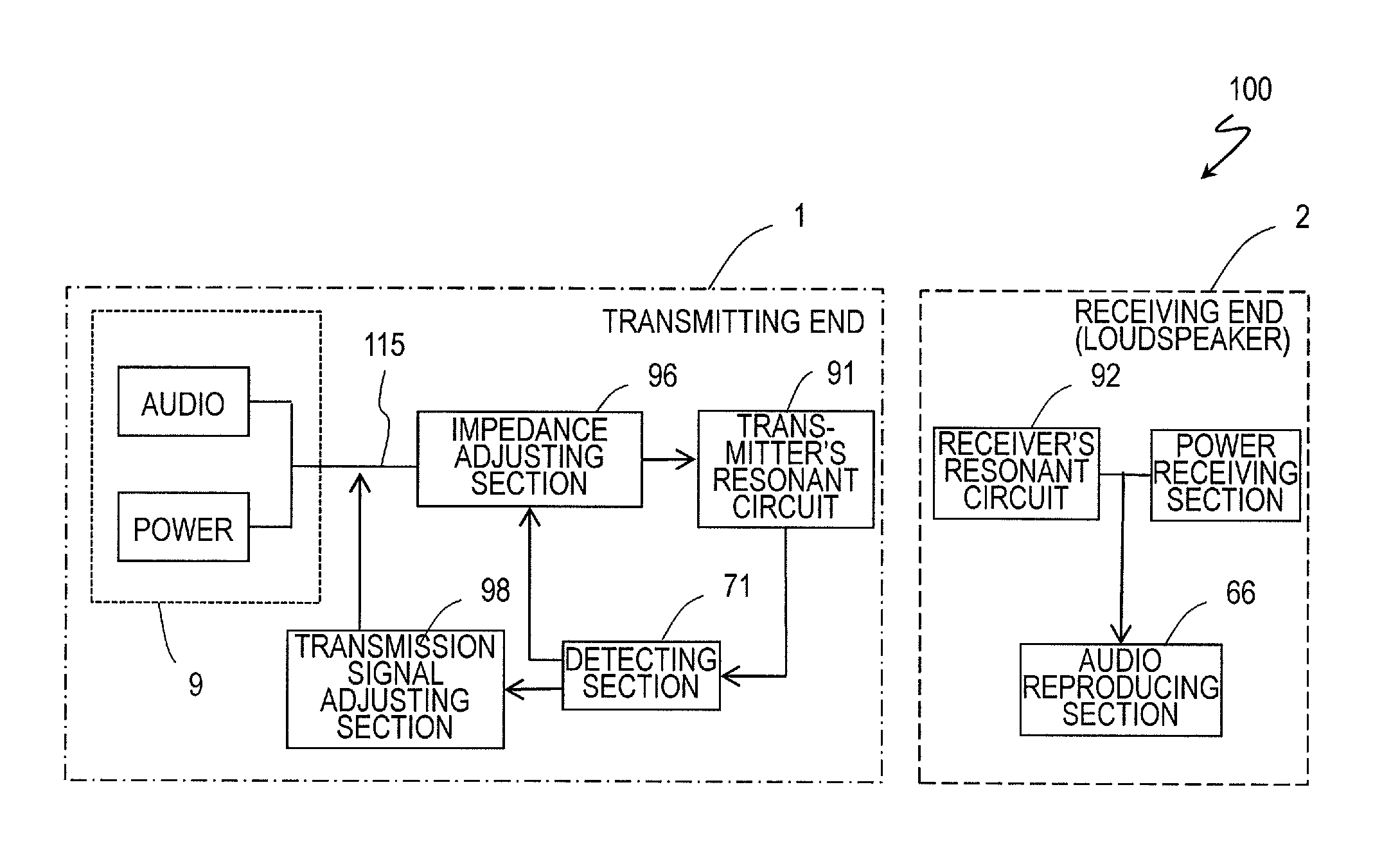
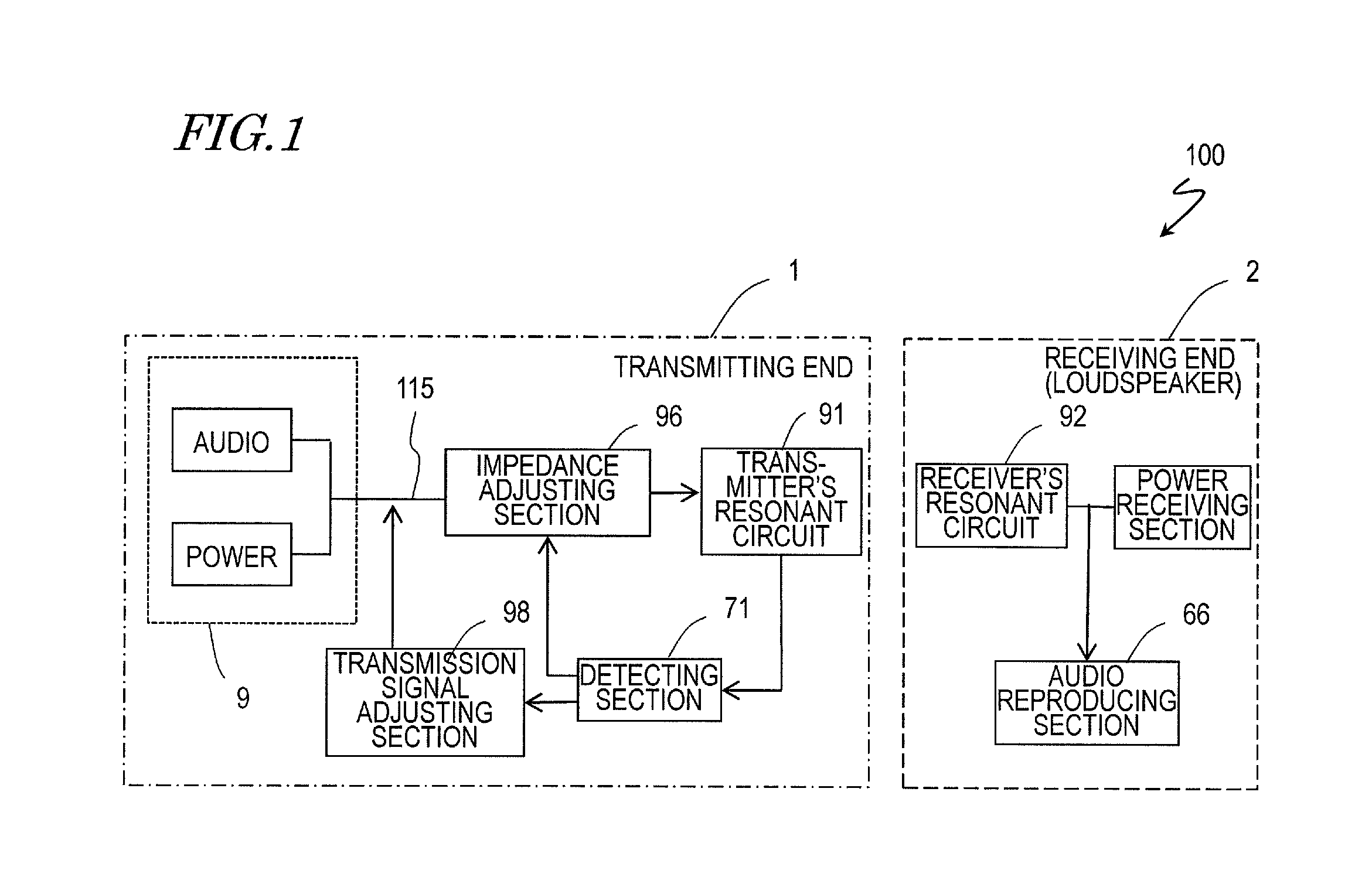
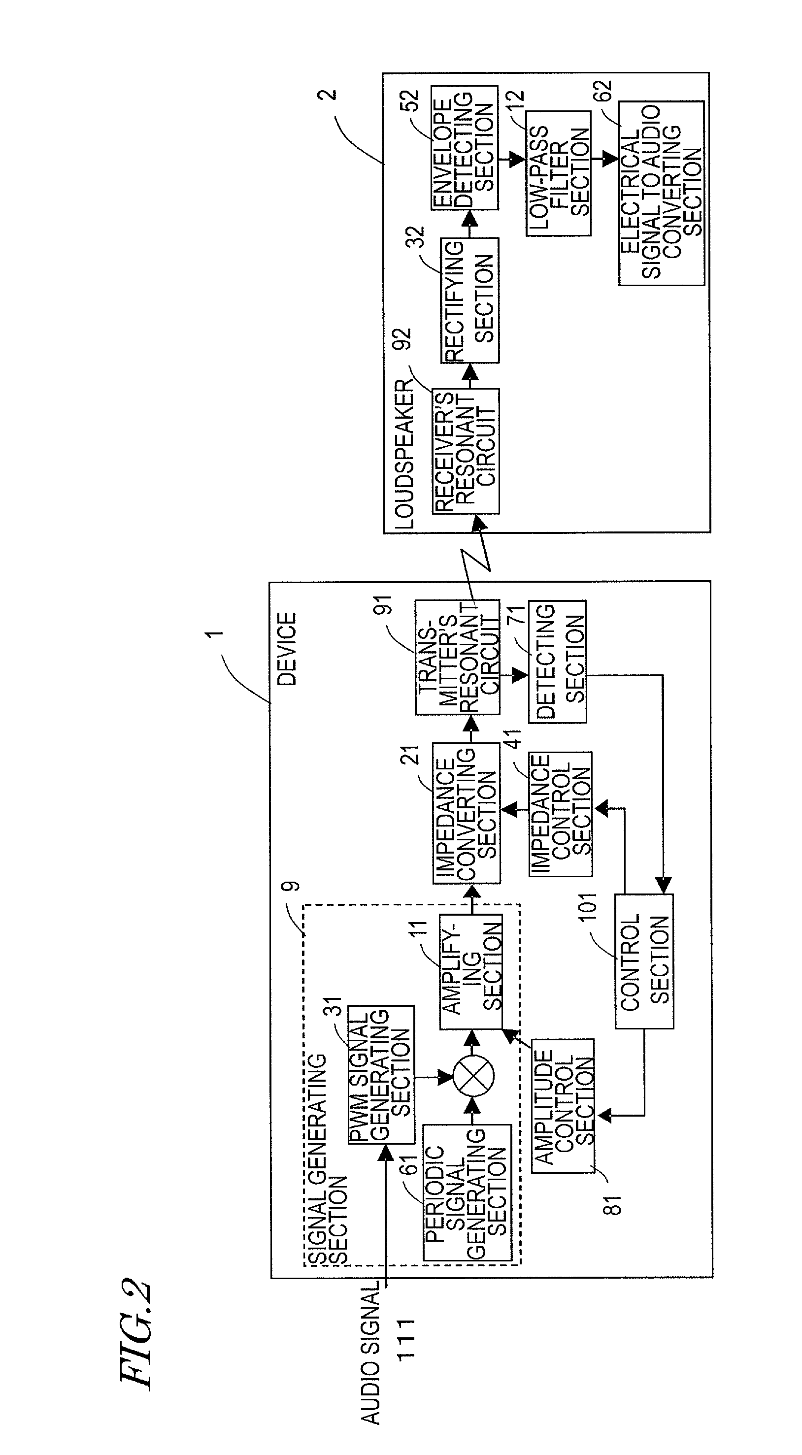
[0082]FIG. 2 illustrates an exemplary arrangement of functional blocks in a wireless power transmission audio system (i.e., a system for transmitting power wirelessly to a loudspeaker) as a first specific preferred embodiment of the present invention. The audio system of this first preferred embodiment is comprised of a device on the transmitting end (which will also be referred to herein as an “audio device”) 1 and a loudspeaker (which function as a device on the receiving end) 2.

[0083]The device 1 includes a signal generating section (which is equivalent to the transmission signal generating section as defined in the claims 9 and a transmitter's resonant circuit 91. The signal generating section 9 includes a PWM signal generating section 31, a periodic signal generating section 61, and an amplifying section 11. The device 1 further includes an impedance converting section and an impedance control section 41, which are used to adjust the impedance, between the signal generating sec...

embodiment 2

[0104]FIG. 7 illustrates an exemplary arrangement of functional blocks in a wireless power transmission audio system as a second preferred embodiment of the present invention. In FIG. 7, any component also included in the wireless power transmission audio system of the first preferred embodiment described above and having substantially the same function as its counterpart is identified by the same reference numeral and description thereof will be omitted herein.

[0105]In the first preferred embodiment described above, the amplification factor of the transmission signal of the amplifying section 11 in the signal generating section 9 is changed in order to prevent the volume of the output audio from changing before and after the impedance value is changed. On the other hand, according to this second preferred embodiment, the variation in the volume of the reproduced audio is reduced by controlling the pulse width of the PWM modulated signal when the PWM signal generating section 31 mod...

embodiment 3

[0112]FIG. 10 illustrates an exemplary arrangement of functional blocks in a wireless power transmission audio system as a third preferred embodiment of the present invention. In FIG. 10, any component also included in the wireless power transmission audio system of the first or second preferred embodiment described above and having substantially the same function as its counterpart is identified by the same reference numeral and description thereof will be omitted herein.

[0113]In the first and second preferred embodiments of the present invention described above, only the device 1 is supposed to be provided with the impedance adjusting section. However, in this third preferred embodiment, both of the device 1 and the loudspeaker 2 include the impedance adjusting section, each of which includes an impedance converting section 21, 22.

[0114]The PWM modulated signal received at the receiver's resonant circuit 92 is rectified by the rectifying section 32. In the meantime, a recycled pow...


PUM


Abstract

The transmitter of a wireless power transmission audio system includes: a transmission signal generating section for generating a transmission signal comprised of an RF signal; a first resonant circuit which receives and sends out the transmission signal; a detecting section for sensing a variation in the transmission signal; and a transmission signal adjusting section. The loudspeaker of the system includes: a second resonant circuit for receiving the transmission signal by producing a magnetic field resonant coupling phenomenon; and an audio output section for reproducing the audio signal. At least one of the transmitter and the loudspeaker includes an impedance adjusting section which changes an impedance value on the transmission line of the transmission signal. When the impedance adjusting section changes the impedance value, the transmission signal adjusting section changes the signal waveform of the transmission signal.

Description

BACKGROUND OF THE INVENTION[0001]1. Field of the Invention[0002]The present invention relates to a wireless power transmission audio system for transmitting wirelessly an audio signal and electric power that drives a loudspeaker and also relates to a device on the transmitting end and a loudspeaker for use in such a system.[0003]2. Description of the Related Art[0004]Recently, as cellphones, terrestrial digital TV broadcasting and their related technologies have been further advanced, wireless receivers that receive text data, audio data and telecasts wirelessly as radio waves without using a cable connection have become more and more popular. Currently, electric power is still supplied through a cable to most of those wireless receivers in order to charge its built-in battery to the point that the device is ready to use. However, as those wireless telecommunications technologies have been developing, a lot of people have been attempting nowadays to transmit electric power, as well ...

Claims


Application Information

Patent Timeline
Patent Type & Authority Applications(United States)
IPC IPC(8): H04B3/00H04B5/02H04R1/06H04R3/00
CPCH04L25/4902H02J17/00H04R2420/07H02J50/12H02J50/80H02J50/90H02J50/20
Inventor KINOSHITA, KEISUKEKAWAMURA, JUNICHIOKAMURA, SHUTAI
Owner PANASONIC INTELLECTUAL PROPERTY MANAGEMENT CO LTD
Why Eureka
Try Eureka